Page 58: of Maritime Reporter Magazine (December 1987)
Read this page in Pdf, Flash or Html5 edition of December 1987 Maritime Reporter Magazine
 57
57
 59
59
MAN GHH Reports
On Design Requirements
For Modern Naval Drydocks
Part II: The Critical Importance Of Block Support 1'6"
A feature article detailing the overall advantages of MAN GHH drydock designs specifically for naval ship applications appeared in the October 1987 issue of Maritime
Reporter and Engineering News.
This second follow-up article ex- amines more closely the critical areas of design and placement of both keel blocks and bilge blocks in order to provide optimum efficiency in accommodating the sometimes unusual hull configurations of naval vessels. Some Navy ships, such as cruisers and destroyers, have hull appendages that protrude beyond the normal keel line—some by a great distance. Protrusion of ap- pendages such as sonar domes, fin stabilizers, rudders and propellers may be as much as 10 feet.
During the drydocking of a ship the areas of block support are very critical, f'or docking there is always a planned program that defines the points of support and the support areas required; each time a ship is docked, the positions are varied slightly so that the whole bottom surface of the ship can be progres- sively inspected and maintained.
To permit precise adjustment of the block heights, the blocking pro- gram allows for deviations from the designed hull configuration by in- cluding the measured profile.
Keel Blocks
Keel blocks are commonly cov- ered with a timber layer which al- lows a more even distribution of the load on the hull contact surface.
The normal bearing width of the . block is 4 feet, however, some ves- sels (e.g. with a pipe tunnel) require blocks wide enough to support both longitudinal bulkheads of the tun- nel. Additionally for offset tunnels a
HARD WOOD
Exhibit 1
KEEL BLOCK block head width between 8 and 10 feet is required.
The block heads designed by
MAN GHH are constructed from steel overlayed by wood with a ta- pered structure toward the pontoon deck that allows an attachment also for the normal 4-foot bearing width.
All keel blocks are removable to per- mit access to the vessel's hull. Ear- lier MAN GHH blocks were fitted with a wedge that could be knocked out for unloading or removing (see
Exhibit 1). Modern blocks are sup- plied with a sandbed design. This method has a bed of sand of approx. 6" depth beneath the timber layer.
During loading the sand settles to give an even distribution of load and for unloading or removal it may be flushed out with water (see Exhibit 2). Normal practice adopted is that once the block is removed, it is not replaced to the same position but set up for use on the next ship to be docked.
A keel block would normally sit on the level pontoon deck. The deck plating of a floating drydock is rein- forced below the keel block posi- tions. For a steel-based keel block structure, as in Exhibit 1 and 2, a cross-bracing below the deck is nor- mally sufficient. A keel block base structure of timber or concrete, as in
Exhibit 3, will require the below deck bracing to be spaced close enough to prevent over-deflection of the deck plating.
Reduction of high block loads can often be achieved by skillful manip- ulation of tank loadings. Particu- larly high loads occur on the end blocks when docking either a short ship in a long dock or a long ship in a short dock. In the first case the dockmaster will attempt to com- pletely unload ballast tanks, this can only be achieved for those tanks that the ship length completely cov- ers. The ship can then only be lifted with the buoyancy produced by the loaded tanks, thus avoiding dock deflection and increase of block loading at the dock ends.
In the second case the following procedure is used: (a) The ship is to
SOFT WOOD
HARD WOOD
SAND
STEEL
Exhibit 2
KEEL BLOCK be supported by a set number of blocks with equal loading on each block, (b) The bending stresses in the hull of the ship in the supported condition may be calculated and checked for safety, (c) The hogging curve of the hull may also be deter- mined. (d) On docking, this pre- determined hogging condition must be achieved, i.e. the actual hogging deflection, with the ship supported, must not be less than the predeter- mined value.
Note: If the predetermined hog- ging deflection is greater than that achievable by experience of the dock characteristics, then the height
Exhibit 3
KEEL BLOCK of the blocks towards the dock ends can be reduced and a new hogging deflection derived.
Clearly, the higher the level of ballast water remaining in the dock tanks after lifting, the greater the level of dock pre-hogging can be achieved (i.e. the lighter the ship).
Bilge Blocks
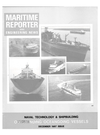
In addition to the keel blocks the ship is supported along both sides by bilge blocks. MAN GHH have adopted the type of construction as shown in Exhibit 4. Basically it con- sists of a pivoted steel beam, one end of which can be raised or low- ered by a mechanical drive system.
This type of block allows complete removal with no projections into the dock area.
During the initial docking of a ship, the bilge blocks are set in their lowest position and are recom- mended only to be used as a means of maintaining the ship upright and stable. When the ship is in its final position fully supported by the keel blocks, then the bilge blocks are raised lightly against the sides of the ship. Then consecutively and pro- gressively as the ship is lifted, each block is lowered and raised to give a light stabilizing load on the hull.
When completed in this manner there will be no undue loads on the bilge blocks and minimum stressing of the ship's skin, particularly im- portant in naval applications.
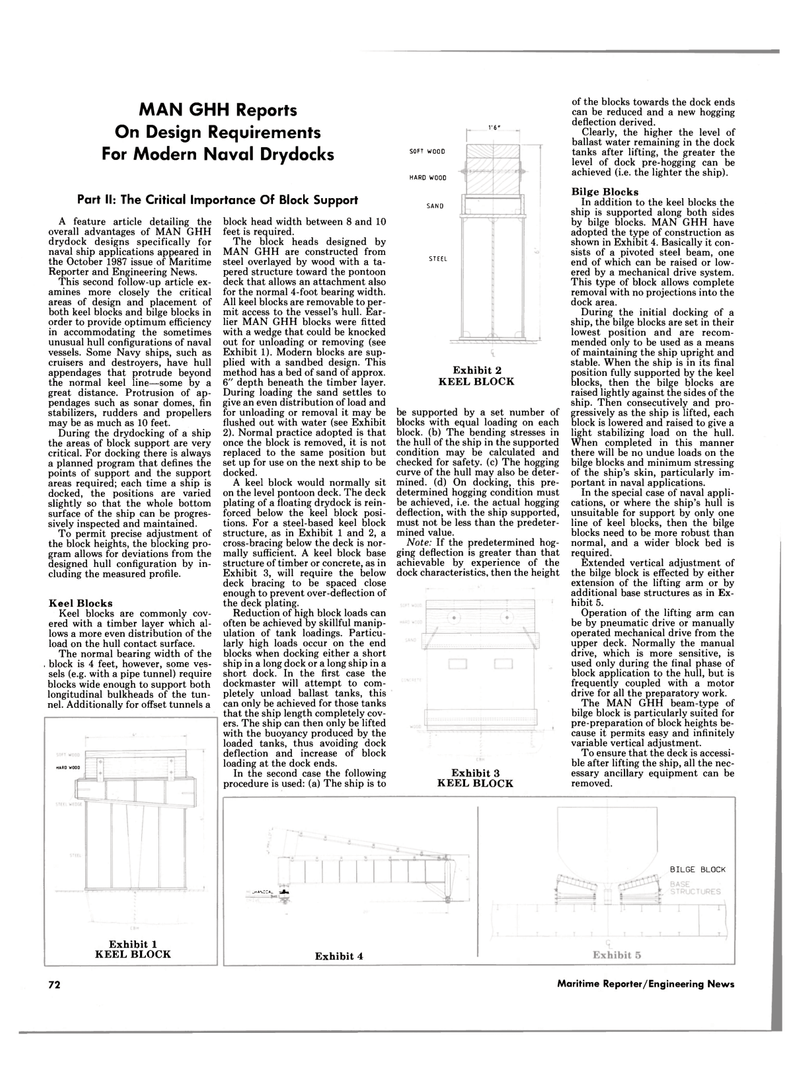
In the special case of naval appli- cations, or where the ship's hull is unsuitable for support by only one line of keel blocks, then the bilge blocks need to be more robust than normal, and a wider block bed is required.
Extended vertical adjustment of the bilge block is effected by either extension of the lifting arm or by additional base structures as in Ex- hibit 5.
Operation of the lifting arm can be by pneumatic drive or manually operated mechanical drive from the upper deck. Normally the manual drive, which is more sensitive, is used only during the final phase of block application to the hull, but is frequently coupled with a motor drive for all the preparatory work.
The MAN GHH beam-type of bilge block is particularly suited for pre-preparation of block heights be- cause it permits easy and infinitely variable vertical adjustment.
To ensure that the deck is accessi- ble after lifting the ship, all the nec- essary ancillary equipment can be removed.
LHANICA^ JLg,
Exhibit 4
BILGE BLOCK 72 Maritime Reporter/Engineering News
