
Page 26: of Maritime Reporter Magazine (May 1994)
Read this page in Pdf, Flash or Html5 edition of May 1994 Maritime Reporter Magazine
 25
25
 27
27
Tanker Technology
ADVANCES IN TANKER PROPULSION
A major VLCC newbuilding program is foreseen by mar- ket analysts who estimate that as many as 300 ships of this size must be replaced up to the end of the decade and into the next century.
It should be recalled that practically no new VLCCs and ULCCs were built from the mid-1970s until a couple of years ago and that the existing ships are coming up for their fourth and fifth surveys, when extensive re- newal of steelwork is likely to be indicated. They will, moreover, have difficulty in meeting the stricter legis- lation and even more strin- gent OPA '90 requirements.
Charterers are imposing more onerous conditions which may be hard to fulfill and it has been reported that the oil majors have a "black list" of owners/op- erators and their ships which are unacceptable.
Today's basic require- ment for propelling machin- ery best suited to a VLCC of around two million barrels (280,000 dwt) capac- ity is for an engine of 20 to 30MW (broadly 27,000 to 40,000bhp) according to the speed and margin required, but at very much lower revolutions than has hitherto been normal; this to take advantage of the higher propulsive efficiency to be gained by a well-designed, very large diam- eter and slow-running propeller.
The capital cost must be competitive, imply- ing a low number of cylinders, and the fuel consumption curve flat and low over a wide range of speeds, typically 55 to 75 rpm.
The main propelling machinery of tankers, as with that for most other types of ships today, can no longer be considered in isolation and choice must take into account the secondary demands for energy on board: for electric and hydraulic power generation, cargo pumping in port and ballast discharge in port and transfer at sea.
This is among the main reasons why steam remained dominant in the tanker field for so long after it became possible and practical to install single diesel engines of appropriate power.* The main boilers also provided steam for turbo-gen- erators, cargo and ballast pump turbines, cargo tank heating and also flue gases of low oxygen content for ullage volume inerting. Weighed against the steam turbine was a specific fuel consumption inherently inferior to that of the diesel engine; a characteristic aggravated dur- ing the 1970s and 1980s when periods of "slow steaming" became necessary while markets were found for the oil they carried. * For some 25 years after WWII almost the only choice for the large tanker was the geared steam turbine. Single diesel engines of sufficient power were not available, without going to many cylinders, involving higher first cost, maintenance effort and a longer and more expensive ship. There were, of course, excep- tions, notable among Scandinavian and Italian owners, who did install high powerdiesel machinery with up to 1 2 cylinders in their then-large tankers. 28
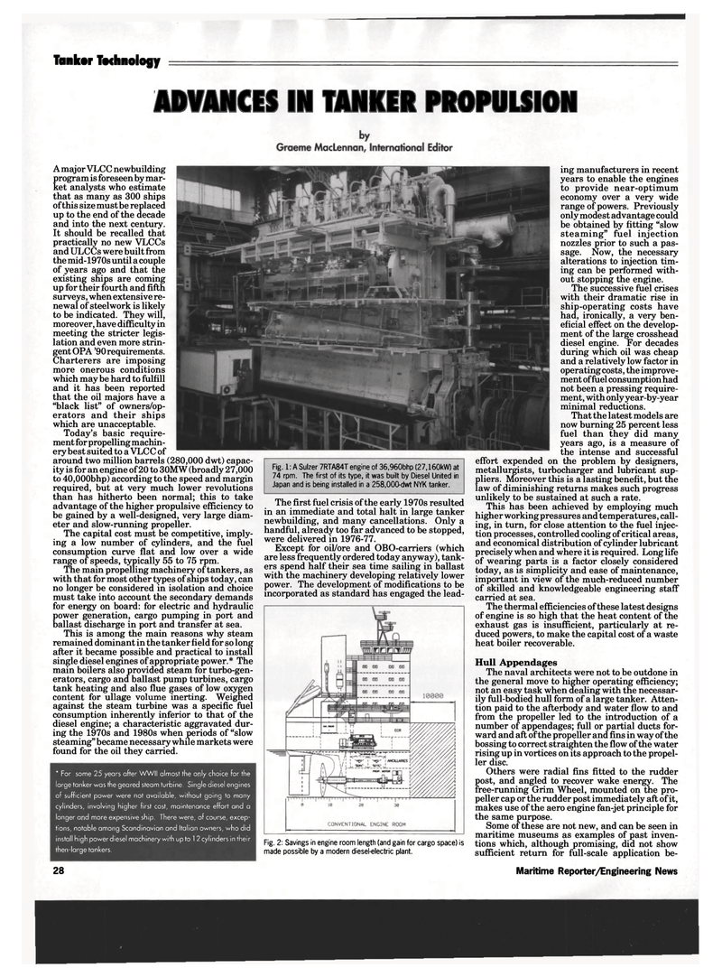
Fig. 1: A Sulzer 7RTA84T engine of 36,960bhp (27,160kW) at 74 rpm. The first of its type, it was built by Diesel United in
Japan and is being installed in a 258,000-dwt NYK tanker.
The first fuel crisis of the early 1970s resulted in an immediate and total halt in large tanker newbuilding, and many cancellations. Only a handful, already too far advanced to be stopped, were delivered in 1976-77.
Except for oil/ore and OBO-carriers (which are less frequently ordered today anyway), tank- ers spend half their sea time sailing in ballast with the machinery developing relatively lower power. The development of modifications to be incorporated as standard has engaged the lead-
Fig. 2: Savings in engine room length (and gain for cargo space) is made possible by a modern diesel-electric plant. ing manufacturers in recent years to enable the engines to provide near-optimum economy over a very wide range of powers. Previously only modest advantage could be obtained by fitting "slow steaming" fuel injection nozzles prior to such a pas- sage. Now, the necessary alterations to injection tim- ing can be performed with- out stopping the engine.
The successive fuel crises with their dramatic rise in ship-operating costs have had, ironically, a very ben- eficial effect on the develop- ment of the large crosshead diesel engine. For decades during which oil was cheap and a relatively low factor in operating costs, the improve- ment of fuel consumption had not been a pressing require- ment, with only year-by-year minimal reductions.
That the latest models are now burning 25 percent less fuel than they did many years ago, is a measure of the intense and successful effort expended on the problem by designers, metallurgists, turbocharger and lubricant sup- pliers. Moreover this is a lasting benefit, but the law of diminishing returns makes such progress unlikely to be sustained at such a rate.
This has been achieved by employing much higher working pressures and temperatures, call- ing, in turn, for close attention to the fuel injec- tion processes, controlled cooling of critical areas, and economical distribution of cylinder lubricant precisely when and where it is required. Long life of wearing parts is a factor closely considered today, as is simplicity and ease of maintenance, important in view of the much-reduced number of skilled and knowledgeable engineering staff carried at sea.
The thermal efficiencies of these latest designs of engine is so high that the heat content of the exhaust gas is insufficient, particularly at re- duced powers, to make the capital cost of a waste heat boiler recoverable.
Hull Appendages
The naval architects were not to be outdone in the general move to higher operating efficiency; not an easy task when dealing with the necessar- ily full-bodied hull form of a large tanker. Atten- tion paid to the afterbody and water flow to and from the propeller led to the introduction of a number of appendages; full or partial ducts for- ward and aft of the propeller and fins in way of the bossing to correct straighten the flow of the water rising up in vortices on its approach to the propel- ler disc.
Others were radial fins fitted to the rudder post, and angled to recover wake energy. The free-running Grim Wheel, mounted on the pro- peller cap or the rudder post immediately aft of it, makes use of the aero engine fan-jet principle for the same purpose.
Some of these are not new, and can be seen in maritime museums as examples of past inven- tions which, although promising, did not show sufficient return for full-scale application be-
Maritime Reporter/Engineering News
