
Page 48: of Maritime Reporter Magazine (April 1998)
Read this page in Pdf, Flash or Html5 edition of April 1998 Maritime Reporter Magazine
 47
47
 49
49
PROPULSION UPDATE tion gear vibration requirements will be met.
The design phase of low noise gearing focus- es on the five areas noted below. In all cases, the basic design objective is to minimize vibra- tion stimuli. • Rotating Elements - maximize balance, roundness, concentricity; • Gear Casing - ensure rotating element support and parallelism; • Bearings - optimize stability; • Couplings - optimize arrangement and shafting system dynamics; and • Mesh Design - maximize uniformity of load transfer.
The benefits of these low noise gearing design features are realized through manufac-
The new generation.
Reliability. Efficiency. Assured quality.
Combining these features, we provide profitability and total economy for offshore support operations. Our optimized supply vessel concept helps you to achieve the essential.
Efficient operations. Everywhere. * •IW
Aquamaster
AZIMUTH THRUSTERS
KAMEWA FINLAND LTD., P.O. Box 220,
FIN-26101 Rauma, Finland
Phone: +358 2 83791, Fax: +358 2 8378 4804.
K A M E WAoroup
EXCELLENCE IN PROPULSION www.kamewagroup.com ^ Part of the Propulsion Technology Division of Vickers PLC
Circle 254 on Reader Service Card 40
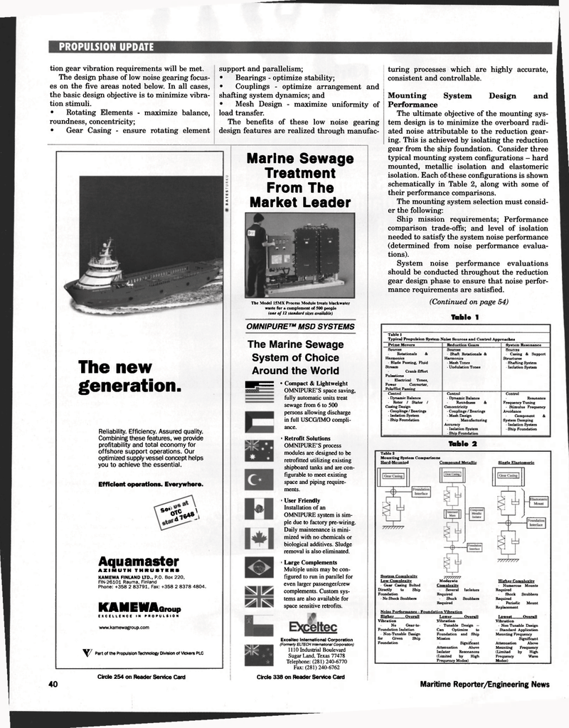
Marine Sewage
Treatment
From The
Market Leader
The Model 15MX Process Module treats blackwater waste for a complement of 500 people (one of 12 standard sizes available)
OMNIPURE™ MSD SYSTEMS
The Marine Sewage
System of Choice
Around the World ^^KSSZ * Compact & Lightweight
OMNIPURE'S space saving, fully automatic units treat sewage from 6 to 500 persons allowing discharge in full USCG/IMO compli- ance. > Retrofit Solutions
OMNIPURE'S process modules are designed to be retrofitted utilizing existing shipboard tanks and are con- figurable to meet existing space and piping require- ments. ' User Friendly
Installation of an
OMNIPURE system is sim- ple due to factory pre-wiring.
Daily maintenance is mini- mized with no chemicals or biological additives. Sludge removal is also eliminated. ' Large Complements
Multiple units may be con- figured to run in parallel for even larger passenger/crew complements. Custom sys- tems are also available for space sensitive retrofits.
Exceltec International Corporation (Formerly ELTECH International Corporation) 1110 Industrial Boulevard
Sugar Land, Texas 77478
Telephone: (281) 240-6770
Fax: (281) 240-6762
Circle 338 on Reader Service Card turing processes which are highly accurate, consistent and controllable.
Mounting System Design and
Performance
The ultimate objective of the mounting sys- tem design is to minimize the overboard radi- ated noise attributable to the reduction gear- ing. This is achieved by isolating the reduction gear from the ship foundation. Consider three typical mounting system configurations - hard mounted, metallic isolation and elastomeric isolation. Each of these configurations is shown schematically in Table 2, along with some of their performance comparisons.
The mounting system selection must consid- er the following:
Ship mission requirements; Performance comparison trade-offs; and level of isolation needed to satisfy the system noise performance (determined from noise performance evalua- tions).
System noise performance evaluations should be conducted throughout the reduction gear design phase to ensure that noise perfor- mance requirements are satisfied. (Continued on page 54)
Table 1
Table 1
Typical Propulsion System Noise Sources and Control Approaches
Prime Movers Reduction Gears System Resonance
Sources
Rotationals &
Harmonics • Blade Passing, Fluid
Stream
Crank-Effort
Pulsations
Electrical Tones,
Power Converter,
Pole/Slot Passing
Sources • Shaft Rotationals &
Harmonics • Mesh Tones • Undulation Tones
Sources • Casing & Support
Structures • Shafting System • Isolation System
Control • Dynamic Balance • Rotor / Stator /
Casing Design • Couplings / Bearings • Isolation System - Ship Foundation
Control - Dynamic Balance
Roundness &
Concentricity • Couplings / Bearings • Mesh Design
Manufacturing
Accuracy • Isolation System • Ship Foundation
Control
Resonance
Frequency Tuning • Stimulus Frequency
Avoidance
Component &
System Damping • Isolation System • Ship Foundation
Table 2
Table 2
Mounting System Comparisons
Hard-Mounted Compound Metallic Single Stagtomeric
System Complexity
Low Complexity • Gear Casing Bolted
Directly to Ship
Foundation • No Shock Snubbers ////////
Moderate
Complexity
Several Isolators
Required
Shock
Required
Snubbers
Noise Performance - Foundation Vibration
Higher Complexity
Numerous Mounts
Required
Shock Snubbers
Required
Periodic Mount
Replacement
Higher Overall
Vibration
No Gear-to-
Foundation Isolation • Non-Tunable Design for Given Ship
Foundation
Lower Overall
Vibration • Tunable Design —
Can Optimize to
Foundation and Ship
Mission
Significant
Attenuation Above
Isolator Resonances (Limited by High
Frequency Modes)
Lowest Overall
Vibration • Non-Tunable Design - Standard Application
Mounting Frequency
Significant
Attenuation Above
Mounting Frequency (Limited by High
Frequency Wave
Modes)
Maritime Reporter/Engineering News
