Page 36: of Maritime Reporter Magazine (May 2, 2010)
Read this page in Pdf, Flash or Html5 edition of May 2, 2010 Maritime Reporter Magazine
 35
35
 37
37
36 Maritime Reporter & Engineering News
Though often tagged with the “conser- vative” label in terms the pace of techno- logical innovation, many sectors of the marine industry are aggressive in devel- oping and delivering innovative solutions to complex problems. The industry today faces the complex problem of reducing emission, fuel consumption and overall its ‘carbon footprint,’ while maintaining a solid bottom line.
There are several vessel designs which incorporate an air-cushioned hull to re- duce resistance when riding through the water, designed to improve fuel effi- ciency and reduce emissions.
DK Group recently announced the launch of the Air Cavity System (ACS)
Retrofit for existing vessels, what it touts as a breakthrough technology, as the de- velopment of the original ACS that was specifically designed for new vessels.
The company claims that the ACS can be retrofitted at standard drydock or in most ship and repair yards in 14 days. ACS
Retrofit, which according to DK Group’s seatrials have shown can reduce fuel con- sumption by up to 15% depending on vessel type, has an average fuel cost pay- back of under two years at current bunker fuel prices, with some ship classes achieving substantially better payback periods. “Few, if any, current efficiency tech- nologies provide such a simple retrofit procedure with such significant payback timelines,” said Ken Bloch Soerensen, the recently appointed CEO of the DK
Group. NYK and Mitsubishi Heavy In- dustries recently reported that they are to begin experiments on an air-lubrication system to reduce CO2 emissions during marine transport. Jointly developed by the two companies, the system is de- signed to reduce the frictional resistance between a vessel's bottom and the seawa- ter by means of bubbles generated by supplying air to the vessel's bottom. The first permanent installation of the system using an air-blower is expected to reduce
CO2 emissions by approximately 10%.
The experiments will be conducted using module carriers -- special heavy load car- riers with RoRo rampway to transport thousand-ton prefabricated structures of plant facilities to be installed on oil/gas development sites, or industrial locations – operated by an NYK Group company,
NYK-Hinode Line, Ltd. Construction of the vessels will be completed in March and November 2010.
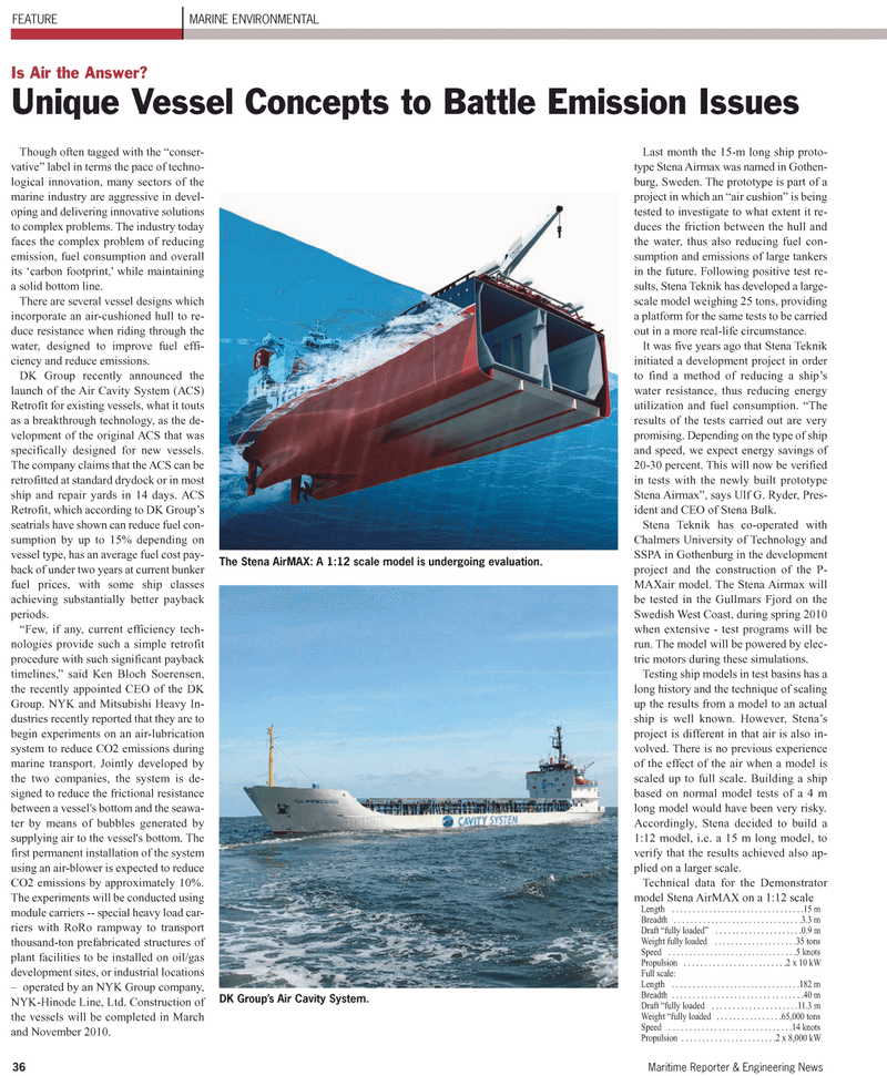
Last month the 15-m long ship proto- type Stena Airmax was named in Gothen- burg, Sweden. The prototype is part of a project in which an “air cushion” is being tested to investigate to what extent it re- duces the friction between the hull and the water, thus also reducing fuel con- sumption and emissions of large tankers in the future. Following positive test re- sults, Stena Teknik has developed a large- scale model weighing 25 tons, providing a platform for the same tests to be carried out in a more real-life circumstance.
It was five years ago that Stena Teknik initiated a development project in order to find a method of reducing a ship’s water resistance, thus reducing energy utilization and fuel consumption. “The results of the tests carried out are very promising. Depending on the type of ship and speed, we expect energy savings of 20-30 percent. This will now be verified in tests with the newly built prototype
Stena Airmax”, says Ulf G. Ryder, Pres- ident and CEO of Stena Bulk.
Stena Teknik has co-operated with
Chalmers University of Technology and
SSPA in Gothenburg in the development project and the construction of the P-
MAXair model. The Stena Airmax will be tested in the Gullmars Fjord on the
Swedish West Coast, during spring 2010 when extensive - test programs will be run. The model will be powered by elec- tric motors during these simulations.
Testing ship models in test basins has a long history and the technique of scaling up the results from a model to an actual ship is well known. However, Stena’s project is different in that air is also in- volved. There is no previous experience of the effect of the air when a model is scaled up to full scale. Building a ship based on normal model tests of a 4 m long model would have been very risky.
Accordingly, Stena decided to build a 1:12 model, i.e. a 15 m long model, to verify that the results achieved also ap- plied on a larger scale.
Technical data for the Demonstrator model Stena AirMAX on a 1:12 scale
Length . . . . . . . . . . . . . . . . . . . . . . . . . . . . . . . .15 m
Breadth . . . . . . . . . . . . . . . . . . . . . . . . . . . . . . .3.3 m
Draft “fully loaded” . . . . . . . . . . . . . . . . . . . . .0.9 m
Weight fully loaded . . . . . . . . . . . . . . . . . . . .35 tons
Speed . . . . . . . . . . . . . . . . . . . . . . . . . . . . . . .5 knots
Propulsion . . . . . . . . . . . . . . . . . . . . . . . . .2 x 10 kW
Full scale:
Length . . . . . . . . . . . . . . . . . . . . . . . . . . . . . . .182 m
Breadth . . . . . . . . . . . . . . . . . . . . . . . . . . . . . . . .40 m
Draft “fully loaded . . . . . . . . . . . . . . . . . . . . .11.3 m
Weight “fully loaded . . . . . . . . . . . . . . . .65,000 tons
Speed . . . . . . . . . . . . . . . . . . . . . . . . . . . . . .14 knots
Propulsion . . . . . . . . . . . . . . . . . . . . . . .2 x 8,000 kW
FEATURE MARINE ENVIRONMENTAL
Is Air the Answer?
Unique Vessel Concepts to Battle Emission Issues
DK Group’s Air Cavity System.
The Stena AirMAX: A 1:12 scale model is undergoing evaluation.
