
Page 76: of Maritime Reporter Magazine (April 2012)
Offshore Deepwater Annual
Read this page in Pdf, Flash or Html5 edition of April 2012 Maritime Reporter Magazine
 75
75
 77
77
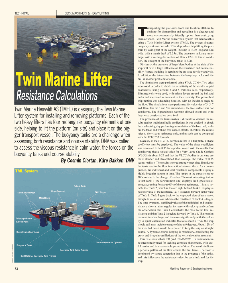
72Maritime Reporter & Engineering News TECHNICALDECK MACHINERY & HEAVY LIFTING Transporting the platforms from one location offshore to onshore for dismantling and recycling is a cheaper and more environmentally friendly option than destroying them offshore. Twin Marine conceived a system that achieves this using a Twin Marine Lifter system (TML). The system features buoyancy tanks on one side of the ship, which help lifting the plat- form by taking part of the weight. The ship is 133m long and 40m wide, with a transit draft of 5.35m. The buoyancy tanks are rather large, with a rectangular section of 10m x 12m. In transit condi- tion, the draught of the buoyancy tanks is 8.9m. Obviously, the presence of large blunt bodies at the side of the ship will have a large influence on the resistance and course sta- bility. Vortex shedding is certain to be an issue for flow analysis. In addition, the interaction between the buoyancy tanks and the hull is another problem to tackle. The simulations were performed using STAR-CCM+. Two grids were used in order to check the sensitivity of the results to grid coarseness, using around 4 and 5 millions cells respectively. Trimmed cells were used, with prisms layers around the hull and tanks and increased refinement in their vicinity. The prescribed ship motion was advancing head-on, with no incidence angle to the flow. The simulations were performed for velocities of 3, 5, 7 and 10kn. For the 3 and 5kn simulations, the free surface was not considered. The ship and tanks were not allowed to sink and trim; they were considered on even keel. The presence of the tanks makes it difficult to validate the re- sults against traditional hulls predictions. It was decided to check the methodology by performing a simulation of the bare hull, with-out the tanks and with no free surface effects. Therefore, the results refer to the viscous resistance only, and as such can be compared with the ITTC 57 formula.Even so, as the ITTC 57 formula refers to a flat plate, a shape coefficient must be employed. The value of the shape coefficient was estimated to be 0.35 for a perfect match with the results. But considering that a typical value for a Very-Large Crude Carriers (VLCCs) is about 0.25 and that the VLCCs bodies in our case are more slender and streamlined than average, the value of 0.35 seems realistic. The results showed strong vortex shedding due to the tanks and to the flow interaction between them. As a conse- quence, the individual and total resistance components display a highly irregular pattern in time. The jumps in the curves close to 200s are due to the change of meshes.The most interesting featureis that Tank 1 (the forwardmost one) displays the highest resist- ance, accounting for about 66% of the total resistance. It is also no-table that Tank 2, which is located right behind Tank 1, displays a positive value of the resistance, i.e. it is sucked forward in the wake of Tank 1. Tank 3 gets back to the expected sign of resistance, though its value is low, whereas the resistance of Tank 4 is larger. The time-averaged, stabilized values of the individual and total re- sistance show a rather regular increase with velocity and confirm the observation that Tank 1 contributes the most to the total re- sistance and that Tank 2 is sucked forward by Tank 1. The rotation moment is rather large, and increases significantly with the veloc- ity. A quick calculation indicates that at a speed of 7kn, the ship should sail at an incidence angle of about 9 degrees. About 12% of the installed thrust would be required to keep the ship on straight course. A dynamic course keeping is mandatory, considering the quick and irregular oscillations of the vertical rotation moment. This case shows that CFD (and STAR-CCM+ in particular) can be successfully used for tackling complex phenomena, with use- ful results and in a reasonable period of time. The results indicate a periodic pattern of the flow around the hull tanks. The flow is dominated by vortex generation due to the presence of the tanks, and this influences the resistance value for each tank and for the ship.Twin Marine Heavylift AS (TMHL) is designing the Twin Marine Lifter system for installing and removing platforms. Each of the two heavy lifters has four rectangular buoyancy elements at one side, helping to lift the platform (on site) and place it on the big-ger transport vessel. The buoyancy tanks are a challenge when assessing both resistance and course stability. DNV was called to assess the viscous resistance in calm water, the forces on the buoyancy tanks and course stability. By Cosmin Ciortan, Kåre Bakken, DNV Twin Marine Lifter Resistance Calculations Skid Rails for Buoyancy Tank Frames Buoyancy Tanks Quick Evacuation Tanks Telescope Beam & Load PointBuoyancy Tank Guide Frames Vertical Hydraulic Cylinder Skid Wagon Ballast Tanks Hinge Support TML SystemSkid Rails on DeckMain Hinge(Images Courtesy: CD Adapco)
