
Page 30: of Maritime Reporter Magazine (January 2013)
Ship Repair & Conversion
Read this page in Pdf, Flash or Html5 edition of January 2013 Maritime Reporter Magazine
 29
29
 31
31
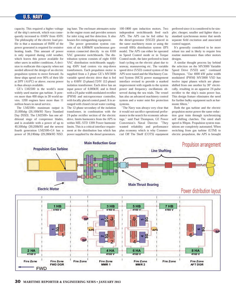
30 MARITIME REPORTER & ENGINEERING NEWS ? JANUARY 2013 capacity. This required a higher voltage of the ship?s network, which was conse- quently increased to 4160V from 450V. The philosophy of the electric load pro-Þ le is that a maximum of 9MW of the power generated is required for resistive heating loads. This amount of power is only required during cold weather, which leaves this power available for other users in milder conditions. A deci- sion to reallocate this capacity when not needed allowed the design of an electric propulsion system to move forward. As these ships spend over 90% of their life at 20ºF (-6.6ºC) or above, excess power is thus always available. GE?s LM2500 is the world?s most widely used marine gas turbine. It pow-ers more than 400 ships in 30 world na-vies. 1200 engines have more than 11 million hours in naval service. The LM2500+ maximum output is 35,000shp (26,100kW) Navy Standard Day (NSD). The LM2500+ has one ad- ditional stage of compressor blades, and is available with a power of up to 40,500shp (30,200kW) and the newest fourth generation LM2500+G4 has a power of 39,240shp (29,280kW) NSD. The LM2500+ marine gas turbine can be housed in a highly shock-resistant, thermal, acoustic enclosure on a mount-ing base. The enclosure attenuates noise in the engine room and provides sensors for inlet icing and Þ re detection. It also houses Þ re extinguishing equipment. The power generation system con-sists of six 4,000kW synchronous gen- erators connected directly to six 4160 VAC generator switchboards. The dis- tribution system consists of eight 4160 VAC distribution switchboards supply- ing 450V load centers via step-down transformers. Each propulsion motor is supplied from a 3 phase GE?s MV3000 variable speed electric drive that is fed by a 4160V (3-phase):724V (12-phase) isolation transformer. Each drive has an input power of 4,000kW, and is Þ tted with a 24 pulse width modulated rectiÞ er (PWM) and microprocessor controller, with locally placed control panel. It is ar- ranged with closed circuit water cooling. The 12-phase secondary of the isolation transformer, in combination with the 24-pulse rectiÞ er section of the electric drive, limits harmonics from the APS to within MIL-STD 1399 Power harmonic limits. This is a critical interface require- ment at the distribution bus which has power supplied by the diesel generators. The 3,678kW (5,000hp) propulsion motors of the APS system are water cooled squirrel cage 3 phase, 592V, 100-1800 rpm induction motors. Two independent switchboards feed each APS. The APS can be fed either by the diesel-generator (SSGD) placed in the same machinery room or using the overall 60Hz distribution system (IPS mode). The APS can either be operated in Speed Control mode or in Torque Control mode, the later preferred to limit load cycling on the electric plant due to seaway, manouvering etc. The variable speed drive (VSD) control system of the APS were tuned and the Machinery Con-trol System (MCS) power management interface revised to provide a marked improvement with regards to the system power and frequency oscillations ob-served during the sea trials. The vessel has also an advanced machinery control system and a water mist Þ re protection systems. ?The Navy was always very clear that it would not sacriÞ ce operational perfor- mance in the search for economic advan-tage,? said Paul Thompson, GE Power Conversion?s Naval Director. ?They wanted reliability and performance plus economy which is why Commer- cial Off The Shelf (COTS) equipment was always going to form the basis for system design. For the APS propulsion motor an AC induction machine was preferred since it is considered to be sim-pler, cheaper, smaller and lighter than a standard synchronous motor that needs separate Þ eld excitation and associated control support. It?s generally considered to be more robust too and is likely to require less routine maintenance than other motors designs.A similar thought process lay behind the selection on the MV3000 Variable Speed Drive (VSD) unit,? continued Thompson. ?Our 4000 kW pulse width modulated (PWM) MV3000 VSD has twelve input phases which are phase-shifted from one another by 30° electri-cally, resulting in an apparent 24-pulse rectiÞ er to the ship?s main power bus. This design feature eliminates the need for further bulky equipment such as har- monic Þ lters.?Both the gas turbine and the electric propulsion motor power the same reduc-tion gear train through synchronizing self shifting clutches. The rated shaft speed is 90rpm. Propulsion system tran-sitions are completely automated. When switching from gas turbine (GTM) to electric propulsion, the APS is brought up to speed, then the GTM reduces pow-er down to idle for Þ ve minutes to cool down, before the APS assumes the com- U.S. NAVYPropulsion arrangement Power distribution layoutMR #1 (26-33).indd 30MR #1 (26-33).indd 301/2/2013 11:49:12 AM1/2/2013 11:49:12 AM
