
Page 19: of Maritime Reporter Magazine (January 2014)
Ship Repair & Conversion Edition
Read this page in Pdf, Flash or Html5 edition of January 2014 Maritime Reporter Magazine
 18
18
 20
20
www.marinelink.com 19 mesh block that rotates about the propel- ler axis, with a sliding interface between the cylindrical mesh block and the sur- rounding fl uid domain. Rudder control surface motions were accounted for by using mesh distortion. As the rudder is defl ected to a new position at each time step, the mesh in this structured block is locally deformed and smoothed. By employing this procedure only a single computational mesh had to be generated for the entire simulation - rather than creating several meshes for various rud- der positions and interpolating between them. Because the rudder mesh motion was integrated into the solution process, less user input was required.
Maneuvering simulations
For the case of constant heading and large depth, the submarine is assumed to be traveling through an infi nite domain of stagnant water. The motion of the submarine is controlled by a 3-bladed propeller, rudder and stern planes. The entire computational mesh including the submarine body is assumed to be mov- ing with the body without any deforma- tion. The fl ow fi eld computations were performed in the inertial frame of refer- ence, which makes the specifi cation of boundary conditions easier. Since the body moves through infi nite volume of stagnant water, the velocity specifi ed at the far fi eld boundaries of the computa- tional domain is zero.
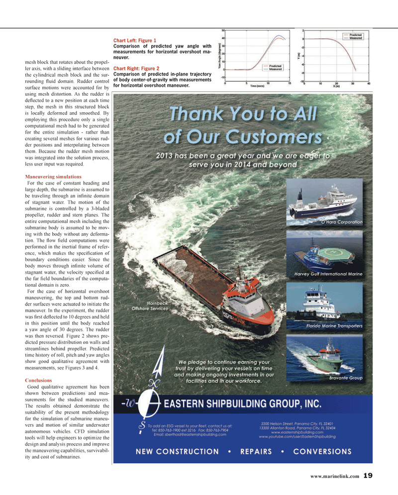
For the case of horizontal overshoot maneuvering, the top and bottom rud- der surfaces were actuated to initiate the maneuver. In the experiment, the rudder was fi rst defl ected to 10 degrees and held in this position until the body reached a yaw angle of 30 degrees. The rudder was then reversed. Figure 2 shows pre- dicted pressure distribution on walls and streamlines behind propeller. Predicted time history of roll, pitch and yaw angles show good qualitative agreement with measurements, see Figures 3 and 4.
Conclusions
Good qualitative agreement has been shown between predictions and mea- surements for the studied maneuvers.
The results obtained demonstrate the suitability of the present methodology for the simulation of submarine maneu- vers and motion of similar underwater autonomous vehicles. CFD simulation tools will help engineers to optimize the design and analysis process and improve the maneuvering capabilities, survivabil- ity and cost of submarines.
Chart Left: Figure 1
Comparison of predicted yaw angle with measurements for horizontal overshoot ma- neuver.
Chart Right: Figure 2
Comparison of predicted in-plane trajectory of body center-of-gravity with measurements for horizontal overshoot maneuver.
MR #1 (18-25).indd 19 1/7/2014 10:23:47 AM
