
Page 26: of Maritime Reporter Magazine (October 2015)
Marine Design Annual
Read this page in Pdf, Flash or Html5 edition of October 2015 Maritime Reporter Magazine
 25
25
 27
27
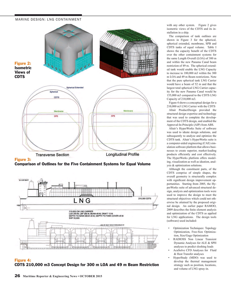
MARINE DESIGN: LNG CONTAINMENT with any other system. Figure 2 gives isometric views of the CDTS and its in- stallation in a ship.
The comparison of tank outlines are shown in Figure 3 for the spherical, spherical extended, membrane, SPB and
CDTS tanks of equal volume. Table I shows the capacity bene? t of the CDTS over the other containment systems for the same Length Overall (LOA) of 300 m and within the new Panama Canal beam
Figure 2: restriction of 49 m. The spherical extend-
Isometric ed tank would enable the LNG Capacity
Views of to increase to 180,000 m3 within the 300 m LOA and 49 m Beam restrictions. Note
CDTS that the pure spherical tank LNG Carrier would have a beam of 52 m and that the largest total spherical LNG Carrier capac- ity for the new Panama Canal would be 155,000 m3 compared to the CDTS LNG
Capacity of 210,000 m3.
Figure 4 shows a conceptual design for a 210,000 m3 LNG Carrier with the CDTS
Altair ProductDesign provided the structural design expertise and technology that was used to complete the develop- ment of the CDTS design, and enabled the
Approval-In-Principle (AIP) from ABS.
Altair’s HyperWorks Suite of software was used to ideate design solutions, and subsequently to analyze and optimize the
CDTS tank. Altair’s HyperWorks suite is a computer-aided engineering (CAE) sim- ulation software platform that allows busi- nesses to create superior, market-leading products ef? ciently and cost effectively.
The HyperWorks platform offers model-
Figure 3: ing, visualization as well as ideation, anal-
Comparison of Outlines for the Five Containment Systems for Equal Volume ysis & optimization solutions.
Although the constituent parts, of the
CDTS comprise of simple shapes, the overall geometry is structurally complex with signi? cant design improvement op- portunities. Starting from 2005, the Hy- perWorks suite of advanced structural de- sign, analysis and optimization tools were used to improve the design to meet the structural objectives which could not oth- erwise be attained by the proposed origi- nal design. An earlier paper RAMOO, 2009 describes the ? nite element analysis and optimization of the CDTS as applied for LNG applications. The design tools (software) used included: • Optimization Techniques: Topology
Optimization, Free-Size Optimiza- tion, Size/Gage Optimization • RADIOSS Non Linear Transient
Dynamic Analyses for ALE & SPH analyses to predict sloshing loads • AcuSolve CFD Analyses for Fluid & Heat Transfer analyses • HyperStudy (MDO) was used to
Figure 4: develop the thermal management strategy such as position, locations,
CDTS 210,000 m3 Concept Design for 300 m LOA and 49 m Beam Restriction and volume of LNG spray-in.
26 Maritime Reporter & Engineering News • OCTOBER 2015
MR #10 (26-33).indd 26 10/2/2015 10:31:34 AM
