
Page 66: of Maritime Reporter Magazine (August 2017)
The Shipyard Edition
Read this page in Pdf, Flash or Html5 edition of August 2017 Maritime Reporter Magazine
 65
65
 67
67
Marine Propulsion
Figure 2
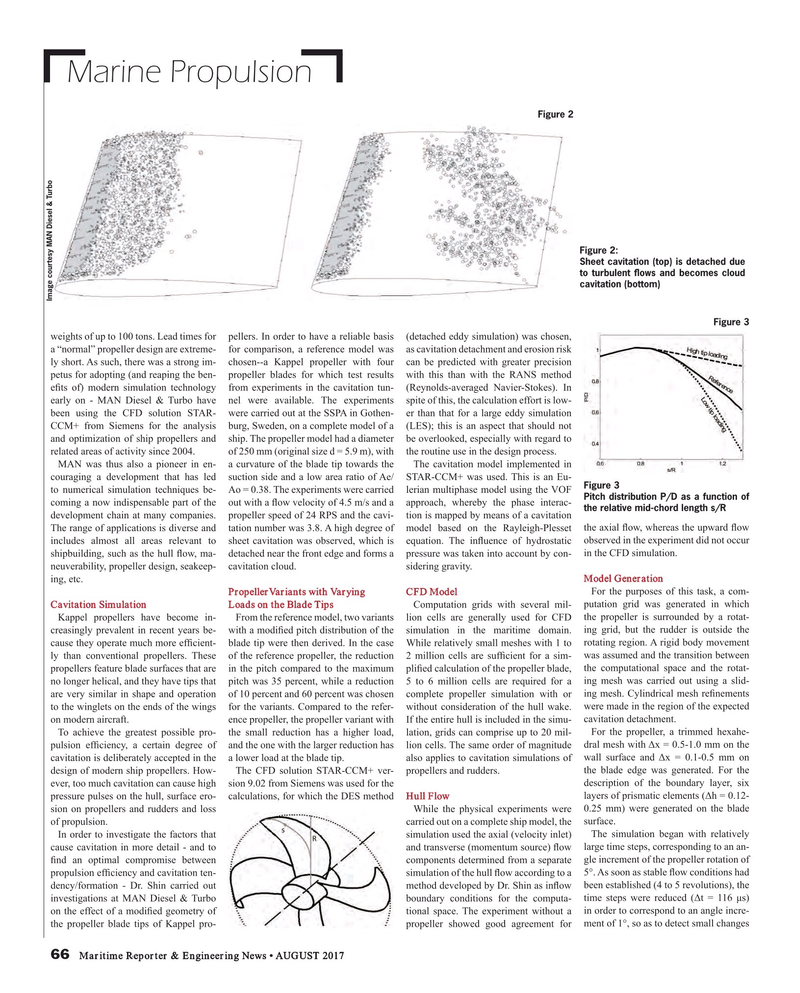
Figure 2:
Sheet cavitation (top) is detached due to turbulent ? ows and becomes cloud cavitation (bottom)
Image courtesy MAN Diesel & Turbo
Figure 3 weights of up to 100 tons. Lead times for pellers. In order to have a reliable basis (detached eddy simulation) was chosen, a “normal” propeller design are extreme- for comparison, a reference model was as cavitation detachment and erosion risk ly short. As such, there was a strong im- chosen--a Kappel propeller with four can be predicted with greater precision petus for adopting (and reaping the ben- propeller blades for which test results with this than with the RANS method e? ts of) modern simulation technology from experiments in the cavitation tun- (Reynolds-averaged Navier-Stokes). In early on - MAN Diesel & Turbo have nel were available. The experiments spite of this, the calculation effort is low- been using the CFD solution STAR- were carried out at the SSPA in Gothen- er than that for a large eddy simulation
CCM+ from Siemens for the analysis burg, Sweden, on a complete model of a (LES); this is an aspect that should not and optimization of ship propellers and ship. The propeller model had a diameter be overlooked, especially with regard to related areas of activity since 2004. of 250 mm (original size d = 5.9 m), with the routine use in the design process.
MAN was thus also a pioneer in en- a curvature of the blade tip towards the The cavitation model implemented in couraging a development that has led suction side and a low area ratio of Ae/ STAR-CCM+ was used. This is an Eu-
Figure 3 to numerical simulation techniques be- Ao = 0.38. The experiments were carried lerian multiphase model using the VOF
Pitch distribution P/D as a function of coming a now indispensable part of the out with a ? ow velocity of 4.5 m/s and a approach, whereby the phase interac- the relative mid-chord length s/R development chain at many companies. propeller speed of 24 RPS and the cavi- tion is mapped by means of a cavitation
The range of applications is diverse and tation number was 3.8. A high degree of model based on the Rayleigh-Plesset the axial ? ow, whereas the upward ? ow includes almost all areas relevant to sheet cavitation was observed, which is equation. The in? uence of hydrostatic observed in the experiment did not occur shipbuilding, such as the hull ? ow, ma- detached near the front edge and forms a pressure was taken into account by con- in the CFD simulation.
neuverability, propeller design, seakeep- cavitation cloud. sidering gravity. ing, etc. Model Generation
PropellerVariants with Varying CFD Model For the purposes of this task, a com-
Cavitation Simulation Loads on the Blade Tips Computation grids with several mil- putation grid was generated in which
Kappel propellers have become in- From the reference model, two variants lion cells are generally used for CFD the propeller is surrounded by a rotat- creasingly prevalent in recent years be- with a modi? ed pitch distribution of the simulation in the maritime domain. ing grid, but the rudder is outside the cause they operate much more ef? cient- blade tip were then derived. In the case While relatively small meshes with 1 to rotating region. A rigid body movement ly than conventional propellers. These of the reference propeller, the reduction 2 million cells are suf? cient for a sim- was assumed and the transition between propellers feature blade surfaces that are in the pitch compared to the maximum pli? ed calculation of the propeller blade, the computational space and the rotat- no longer helical, and they have tips that pitch was 35 percent, while a reduction 5 to 6 million cells are required for a ing mesh was carried out using a slid- are very similar in shape and operation of 10 percent and 60 percent was chosen complete propeller simulation with or ing mesh. Cylindrical mesh re? nements to the winglets on the ends of the wings for the variants. Compared to the refer- without consideration of the hull wake. were made in the region of the expected on modern aircraft. ence propeller, the propeller variant with If the entire hull is included in the simu- cavitation detachment.
To achieve the greatest possible pro- the small reduction has a higher load, lation, grids can comprise up to 20 mil- For the propeller, a trimmed hexahe- pulsion ef? ciency, a certain degree of and the one with the larger reduction has lion cells. The same order of magnitude dral mesh with ?x = 0.5-1.0 mm on the cavitation is deliberately accepted in the a lower load at the blade tip. also applies to cavitation simulations of wall surface and ?x = 0.1-0.5 mm on design of modern ship propellers. How- The CFD solution STAR-CCM+ ver- propellers and rudders. the blade edge was generated. For the ever, too much cavitation can cause high sion 9.02 from Siemens was used for the description of the boundary layer, six pressure pulses on the hull, surface ero- calculations, for which the DES method Hull Flow layers of prismatic elements (?h = 0.12- sion on propellers and rudders and loss While the physical experiments were 0.25 mm) were generated on the blade of propulsion. carried out on a complete ship model, the surface.
In order to investigate the factors that simulation used the axial (velocity inlet) The simulation began with relatively cause cavitation in more detail - and to and transverse (momentum source) ? ow large time steps, corresponding to an an- ? nd an optimal compromise between components determined from a separate gle increment of the propeller rotation of propulsion ef? ciency and cavitation ten- simulation of the hull ? ow according to a 5°. As soon as stable ? ow conditions had dency/formation - Dr. Shin carried out method developed by Dr. Shin as in? ow been established (4 to 5 revolutions), the investigations at MAN Diesel & Turbo boundary conditions for the computa- time steps were reduced (?t = 116 µs) on the effect of a modi? ed geometry of tional space. The experiment without a in order to correspond to an angle incre- the propeller blade tips of Kappel pro- propeller showed good agreement for ment of 1°, so as to detect small changes 66 Maritime Reporter & Engineering News • AUGUST 2017
MR #8 (66-73).indd 66 MR #8 (66-73).indd 66 8/7/2017 2:47:11 PM8/7/2017 2:47:11 PM
