
Page 41: of Maritime Reporter Magazine (June 2024)
Read this page in Pdf, Flash or Html5 edition of June 2024 Maritime Reporter Magazine
 40
40
 42
42
CFD & VESSEL VENTILATION
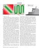
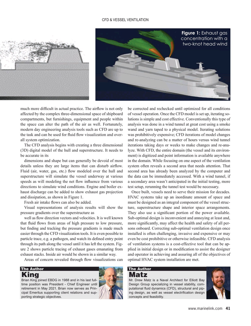
Figure 1: Exhaust gas concentration with a two-knot head wind much more dif? cult in actual practice. The air? ow is not only be corrected and rechecked until optimized for all conditions affected by the complex three-dimensional space of shipboard of vessel operation. Once the CFD model is set up, iterating so- compartments, but furnishings, equipment and people within lutions is simple and cost effective. Conventionally this type of the space can alter the path of the air as well. Fortunately, analysis was done in a wind tunnel at great cost using a smoke modern day engineering analysis tools such as CFD are up to wand and yarn taped to a physical model. Iterating solutions the task and can be used for ? uid ? ow visualization and over- was prohibitively expensive; CFD iterations of model changes all system optimization. and re-analyzing can be a matter of hours versus wind tunnel
The CFD analysis begins with creating a three dimensional iterations taking days or weeks to make changes and re-ana- (3D) digital model of the hull and superstructure. It needs to lyze. With CFD, the entire domain (the vessel and its environ- be accurate in its ment) is digitized and point information is available anywhere dimensions and shape but can generally be devoid of most in the domain. While focusing on one aspect of the ventilation details unless they are large items that can disturb air? ow. system often reveals a second area that needs attention. That
Fluid (air, water, gas, etc.) ? ow modeled over the hull and second area has already been analyzed by the computer and superstructure will simulate the vessel underway at various the data can be immediately accessed. With a wind tunnel, if speeds as will modeling the net ? ow in? uence from various a secondary area wasn’t anticipated in the initial testing, more directions to simulate wind conditions. Engine and boiler ex- test setup, rerunning the tunnel test would be necessary.
haust discharge can be added to show exhaust gas projection Once built, vessels need to serve their mission for decades. and dissipation, as shown in Figure 1. HVAC systems take up an inordinate amount of space and
Fresh air intake ? ows can also be added. must be designed as an integral component of the vessel struc-
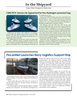
Visual representations of analysis results will show the ture, superstructure shape and interior space arrangements. pressure gradients over the superstructure as They also use a signi? cant portion of the power available. well as ? ow direction vectors and velocities. It is well known Sub-optimal design is inconvenient and annoying at least and, that ? uid ? ows from areas of high pressure to low pressure, more signi? cantly, may affect the health and safety of all per- but ? nding and tracking the pressure gradients is made much sons onboard. Correcting sub-optimal ventilation design once easier through the CFD visualization tools. It is even possible to installed is often challenging, invasive and expensive or may particle trace, e.g. a pathogen, and watch its de? ned entry point even be cost prohibitive or otherwise infeasible. CFD analysis through its path along the vessel until it has left the system. Fig- of ventilation systems is a cost-effective tool that can be ap- ure 2 shows particle tracing of exhaust gases emanating from plied in initial design or in modi? cation to assist the designer exhaust stacks. Inside air would be shown in a similar way. and operator in achieving and assuring all of the objectives of
Areas of concern revealed through ? ow visualizations can optimal HVAC system installation are met.
The Author The Author
King Matz
Brian King joined EBDG in 1988 and in his last full- Mr. Drew Matz is a Naval Architect for Elliott Bay time position was President - Chief Engineer until Design Group specializing in vessel stability, com- retirement in May 2021. Brian now serves as Prin- putational ? uid dynamics (CFD), structural and pip- cipal Emeritus supporting client relations and sup- ing design, as well as vessel electri? cation design porting strategic objectives. concepts and feasibility. www.marinelink.com 41
MR #6 (34-44).indd 41 6/3/2024 11:56:44 AM
