
Page 59: of Offshore Engineer Magazine (Mar/Apr 2014)
Read this page in Pdf, Flash or Html5 edition of Mar/Apr 2014 Offshore Engineer Magazine
 58
58
 60
60
Pipelines
S-lay accumulated plastic strain that the pipe- or less constant, but the strain continues
The vessel will be able to carry 8500- line experiences, as it is repeatedly bent to increase, until the pipe bend radius tonne of rigid pipe on/below deck, like and straightened. This should be as low matches that of the aligner wheel. an s-lay barge, which is 50% more than as possible, particularly for deepwater The pipe is held to the formed radius its nearest competitor. Instead of laying applications. of the deck aligner wheel by the ten- the pipe over a stern stinger, it will be
The extent of the accumulated strain sion in the pipeline. If that tension were de? ected forward, around to be removed, the pipe a deck aligner wheel. would elastically spring
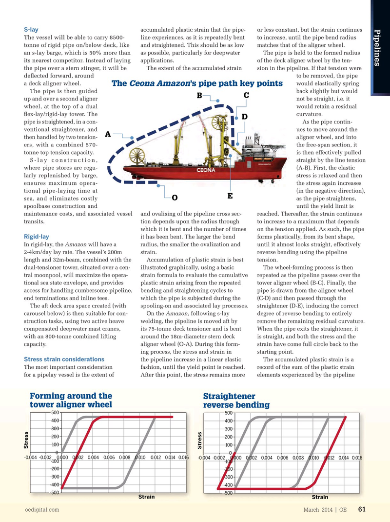
The ’s pipe path key pointsCeona Amazon
The pipe is then guided back slightly but would
B C up and over a second aligner not be straight, i.e. it wheel, at the top of a dual would retain a residual ? ex-lay/rigid-lay tower. The curvature.
D pipe is straightened, in a con- As the pipe contin- ventional straightener, and ues to move around the
A then handled by two tension- aligner wheel, and into ers, with a combined 570- the free-span section, it tonne top tension capacity. is then effectively pulled
S-lay construction, straight by the line tension where pipe stores are regu- (A-B). First, the elastic larly replenished by barge, stress is relaxed and then ensures maximum opera- the stress again increases tional pipe-laying time at (in the negative direction),
E sea, and eliminates costly as the pipe straightens,
O spoolbase construction and until the yield limit is maintenance costs, and associated vessel and ovalising of the pipeline cross sec- reached. Thereafter, the strain continues transits. tion depends upon the radius through to increase to a maximum that depends which it is bent and the number of times on the tension applied. As such, the pipe
Rigid-lay it has been bent. The larger the bend forms plastically, from its bent shape,
In rigid-lay, the Amazon will have a radius, the smaller the ovalization and until it almost looks straight, effectively 2-4km/day lay rate. The vessel’s 200m strain. reverse bending using the pipeline length and 32m-beam, combined with the Accumulation of plastic strain is best tension.
dual-tensioner tower, situated over a cen- illustrated graphically, using a basic The wheel-forming process is then tral moonpool, will maximize the opera- strain formula to evaluate the cumulative repeated as the pipeline passes over the tional sea state envelope, and provides plastic strain arising from the repeated tower aligner wheel (B-C). Finally, the
Werft Bremerhaven, in Bremerhaven, access for handling cumbersome pipeline, bending and straightening cycles to pipe is drawn from the aligner wheel where the vessel is undergoing ? nish- end terminations and inline tees. which the pipe is subjected during the (C-D) and then passed through the ing. It will then move to Huisman’s yard The aft deck area space created (with spooling-on and associated lay processes. straightener (D-E), inducing the correct in Schiedam, the Netherlands, where carousel below) is then suitable for con- On the Amazon, following s-lay degree of reverse bending to entirely its two, 400-tonne capacity, heavy load struction tasks, using two active heave welding, the pipeline is moved aft by remove the remaining residual curvature. cranes, and the 570-tonne pipelay tower compensated deepwater mast cranes, its 75-tonne deck tensioner and is bent When the pipe exits the straightener, it will be ? tted. with an 800-tonne combined lifting around the 18m-diameter stern deck is straight, and both the stress and the
The Amazon has been designed to capacity. aligner wheel (O-A). During this form- strain have come full circle back to the combine proven s-lay and rigid-lay ing process, the stress and strain in starting point.
Stress strain considerations construction equipment, in a con? gu- the pipeline increase in a linear elastic The accumulated plastic strain is a
The most important consideration fashion, until the yield point is reached. record of the sum of the plastic strain ration that optimizes deck space and for a pipelay vessel is the extent of After this point, the stress remains more elements experienced by the pipeline ef? ciency.
Straightening in the free-span Forming around the Straightener between aligner wheels tower aligner wheel reverse bending 500 500 500 400 400 400 300 300 300 200 200 200 100 100 100
Stress
Stress
Stress 0 0 0 -0.004 -0.002 0.000 0.002 0.004 0.006 0.008 0.010 0.012 0.014 0.016 -0.004 -0.002 0.000 0.002 0.004 0.006 0.008 0.010 0.012 0.014 0.016 -0.004 -0.002 0.000 0.002 0.004 0.006 0.008 0.010 0.012 0.014 0.016 -100 -100 -100 -200 -200 -200 -300 -300 -300 -400 -400 -400 -500 -500 -500
Strain Strain Strain oedigital.com March 2014 | OE 61 000_OE0314Pipelines2.indd 61 2/21/14 1:03 PM