
Page 30: of Offshore Engineer Magazine (Mar/Apr 2017)
Read this page in Pdf, Flash or Html5 edition of Mar/Apr 2017 Offshore Engineer Magazine
 29
29
 31
31
con? gurations, making it potentially
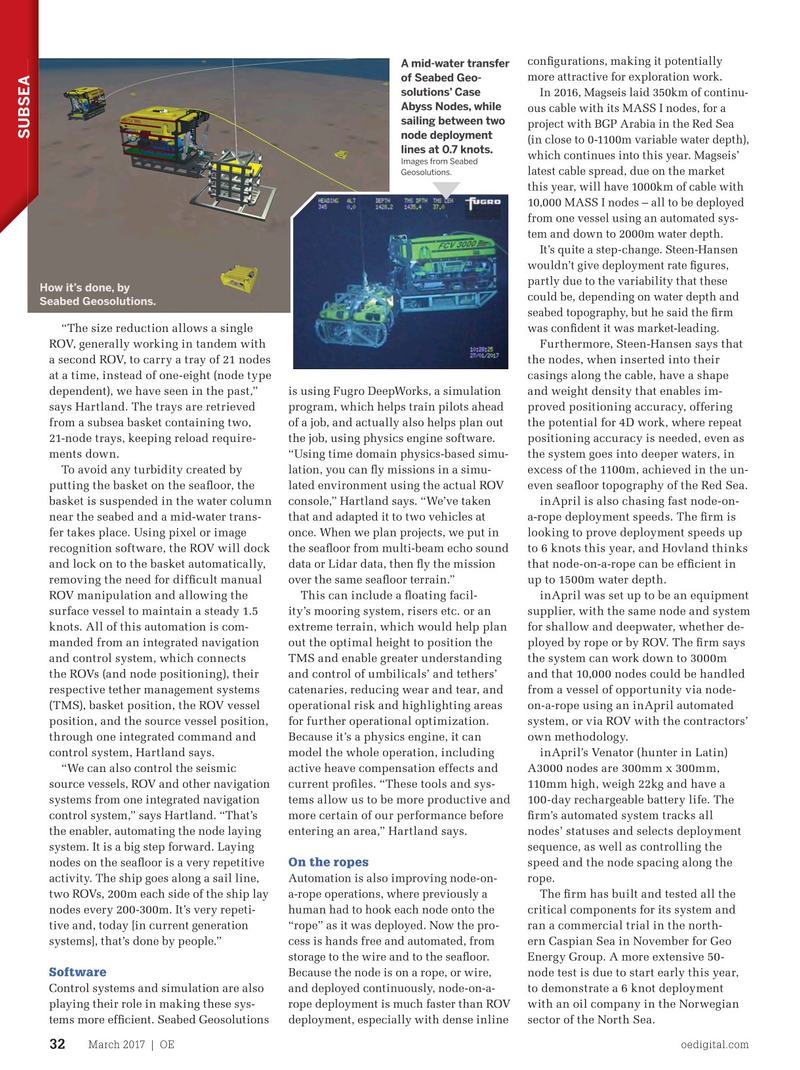
A mid-water transfer more attractive for exploration work. of Seabed Geo- solutions’ Case
In 2016, Magseis laid 350km of continu-
Abyss Nodes, while ous cable with its MASS I nodes, for a sailing between two project with BGP Arabia in the Red Sea node deployment
SUBSEA (in close to 0-1100m variable water depth), lines at 0.7 knots. which continues into this year. Magseis’
Images from Seabed latest cable spread, due on the market
Geosolutions.
this year, will have 1000km of cable with 10,000 MASS I nodes – all to be deployed from one vessel using an automated sys- tem and down to 2000m water depth.
It’s quite a step-change. Steen-Hansen wouldn’t give deployment rate ? gures, partly due to the variability that these
How it’s done, by could be, depending on water depth and
Seabed Geosolutions. seabed topography, but he said the ? rm “The size reduction allows a single was con? dent it was market-leading.
ROV, generally working in tandem with Furthermore, Steen-Hansen says that a second ROV, to carry a tray of 21 nodes the nodes, when inserted into their at a time, instead of one-eight (node type casings along the cable, have a shape dependent), we have seen in the past,” is using Fugro DeepWorks, a simulation and weight density that enables im- says Hartland. The trays are retrieved program, which helps train pilots ahead proved positioning accuracy, offering from a subsea basket containing two, of a job, and actually also helps plan out the potential for 4D work, where repeat 21-node trays, keeping reload require- the job, using physics engine software. positioning accuracy is needed, even as ments down. “Using time domain physics-based simu- the system goes into deeper waters, in
To avoid any turbidity created by lation, you can ? y missions in a simu- excess of the 1100m, achieved in the un- putting the basket on the sea? oor, the lated environment using the actual ROV even sea? oor topography of the Red Sea. basket is suspended in the water column console,” Hartland says. “We’ve taken inApril is also chasing fast node-on- near the seabed and a mid-water trans- that and adapted it to two vehicles at a-rope deployment speeds. The ? rm is fer takes place. Using pixel or image once. When we plan projects, we put in looking to prove deployment speeds up recognition software, the ROV will dock the sea? oor from multi-beam echo sound to 6 knots this year, and Hovland thinks and lock on to the basket automatically, data or Lidar data, then ? y the mission that node-on-a-rope can be ef? cient in removing the need for dif? cult manual over the same sea? oor terrain.” up to 1500m water depth.
ROV manipulation and allowing the This can include a ? oating facil- inApril was set up to be an equipment surface vessel to maintain a steady 1.5 ity’s mooring system, risers etc. or an supplier, with the same node and system knots. All of this automation is com- extreme terrain, which would help plan for shallow and deepwater, whether de- manded from an integrated navigation out the optimal height to position the ployed by rope or by ROV. The ? rm says and control system, which connects TMS and enable greater understanding the system can work down to 3000m the ROVs (and node positioning), their and control of umbilicals’ and tethers’ and that 10,000 nodes could be handled respective tether management systems catenaries, reducing wear and tear, and from a vessel of opportunity via node- (TMS), basket position, the ROV vessel operational risk and highlighting areas on-a-rope using an inApril automated position, and the source vessel position, for further operational optimization. system, or via ROV with the contractors’ through one integrated command and Because it’s a physics engine, it can own methodology. control system, Hartland says. model the whole operation, including inApril’s Venator (hunter in Latin) “We can also control the seismic active heave compensation effects and A3000 nodes are 300mm x 300mm, source vessels, ROV and other navigation current pro? les. “These tools and sys- 110mm high, weigh 22kg and have a systems from one integrated navigation tems allow us to be more productive and 100-day rechargeable battery life. The control system,” says Hartland. “That’s more certain of our performance before ? rm’s automated system tracks all the enabler, automating the node laying entering an area,” Hartland says. nodes’ statuses and selects deployment system. It is a big step forward. Laying sequence, as well as controlling the
On the ropes nodes on the sea? oor is a very repetitive speed and the node spacing along the
Automation is also improving node-on- activity. The ship goes along a sail line, rope. a-rope operations, where previously a two ROVs, 200m each side of the ship lay The ? rm has built and tested all the human had to hook each node onto the nodes every 200-300m. It’s very repeti- critical components for its system and “rope” as it was deployed. Now the pro- tive and, today [in current generation ran a commercial trial in the north- cess is hands free and automated, from systems], that’s done by people.” ern Caspian Sea in November for Geo storage to the wire and to the sea? oor.
Energy Group. A more extensive 50-
Software
Because the node is on a rope, or wire, node test is due to start early this year,
Control systems and simulation are also to demonstrate a 6 knot deployment and deployed continuously, node-on-a- playing their role in making these sys- with an oil company in the Norwegian rope deployment is much faster than ROV tems more ef? cient. Seabed Geosolutions sector of the North Sea. deployment, especially with dense inline
March 2017 | OE oedigital.com 32 030_OE0217_Subsea2_subsea nodes.indd 32 2/21/17 6:44 PM