
Esso Norway Test Of Hull Structure Proves Design And Good Workmanship
From June 28 to July 7, 1969, the new 190,- 800-dwt tanker Esso Norway lay at anchor in Eckernfoerde Bay, about 20 miles from Kiel, Germany, where she was built. Figure 1 gives the general arrangement and dimensions of this ship.
An extensive static structural test program was carried out on a continuous round-theclock basis during this period. The objective was to measure the structural response of the internal framing system to a wide range of cargo-tank loadings (salt water ballast) at drafts ranging from about 23 feet to about 60 feet. Counted as parts of the internal framing system in this sense are the longitudinal and transverse ibulkheads, as well as the longitudinal girders and transverse webs.
Approximately 1,400 strain gages had been installed at the shipyard, and strain readings were registered by a scanning system during each of 17 "runs." In this context a "run" is defined as a period of data-taking while ballast was held constant according to the planned schedule. The time required for a run was usually about half an hour.
At 27 points on the deck, vertical deflections from a laser-established base plane were measured; see Figure 1. At six points in the bottom grillage a taut-wire system measured vertical deflections relative to the deck. These grillage deflections showed nothing unexpected and are not discussed in this paper. The entire instrumentation system was designed and monitored during the test program by Germanischer Lloyd of Hamburg, in accordance with requirements established by Esso International.
Following the static test program, some instrumentation was left on board and used for a limited program of dynamic observations during the first or ballast voyage of the ship.
Prior to this, but after completion of the 17 test runs programmed for the static investigations, three additional runs were made specifically for correlation with the dynamic tests.
This part -of the test program forms a separate entity not covered in this paper.
The planning and execution of this test program were stimulated and influenced largely by some unexpected structural behavior in earlier large tankers. The degree of size extrapolation in the design of these huge ships was unprecedented. There was widespread concern about the structural response of the internals under extreme loading conditions, particularly of the deep transverse members of the center 'bottom and wing-tank structures.
This is really a matter of transverse, or secondary strength, mainly influenced by static pressures. Wave pressures and corresponding acceleration loadings play a minor part in the design of the transverse structure.
Deficiencies which had been noted in earlier ships were largely of a type shown by buckling or bulging of large internal plate areas.
In this usage, "buckling" is intended to mean elastic deformation and "bulging" plastic deformation.
There had been some minor cracking of plates, but none of catastrophic proportions so far as is known. Damages and catastrophies caused by collisions, explosions, groundings, and similar events are excluded.
Therefore, the focus of this program was on systematically examining the behavior of important internal plate areas together with their stiffening systems. This was done by correlating measured strains and deflections with load and draft conditions, and by checking possible buckling and bulging situations closely.
The program was planned so that analysis of the experimental data might indicate safety factors and adequacy of current designs, and lead toward improvements in future practice.
No excessive loadings were intentionally placed on any tank boundaries, and it was reassuring to note, on the basis of examinations of tank interiors, that no permanent visible damage occurred during or after the testing.
Clearly, the ship was carefully constructed, with excellent workmanship. The quality of workmanship plays a large part in the vulnerability of plated structure to instabilities, and in particular to permanent buckling or bulging. iNone of this whatever was to be seen, and therefore it can be said with assurance that the tests in no way damaged the ship structure.
The results of the measurements were processed by Germanischer Lloyd in two volumes, titled "Full-Scale Tanker Investigation, Esso Norway, Part A." The first gives a very brief description of the test program, the instrumentation procedures, and measurement results, largely in graphic form. The second is the Appendix under the same title, giving the computer output of the programs which trans-formed strains to stresses and deflections.
Planning the Tests Instrumentation other than that for primary ship-girder deflection (the laser system) was limited to a single "tank group," consisting of center tank and adjacent wing tanks bounded by two adjacent oil-tight transverse bulkheads.
Tanks Nos. 1 and 5 are clearly areas of special structural configuration due to the form of the ship, and are longer than the other tanks.
No. 4 tank contains the flume system, and was eliminated from consideration on this account.
The remaining two tank groups, namely. Nos.
2 and 3, are identical in structure; both having repetitive structural internal stiffening systems and are part of the parallel middle body. Special considerations such as tank coating problems led finally to the decision to instrument part of tank group >No. 3 rather than No. 2.
Advantage was taken of structural and load symmetry wherever possible in order to reduce the amount of instrumentation.
Load Conditions If ballast heights above the baseline in tank groups 2, 3, and 4 were limited to extremes (i.e., either full or empty) symmetrical about the mid-length of tank No. 3, there are 16 possible combinations of loading in the nine tanks which make up these groups. However, due to the flume openings in group No. 4, ballast levels in all three tanks of that group are always identical and the symmetry requirement imposes the same limitation on the tanks in group No. 2. This circumstance reduces the possible number of tank combinations from 16 to eight, provided, of course, that only the two extremes are acceptable, i.e., as near completely full or completely empty as possible.
The net pressure loadings on the envelope boundaries of a tank result from internal pressures due to tank loads and external pressures governed by draft. Because the objective here was to measure under extreme conditions, each of these eight tank-load combinations was studied with respect to the possibility of running at two extreme drafts — namely, light draft (about 23 feet) and full-load draft (about 60 feet). This produced 16 possible test-run combinations, counting draft as one of the variables.
Obviously, some of these 16 combinations of tank loading and draft would be impossible.
For example, to bring the ship down to fullload draft with all tanks of groups Nos. 2, 3, and 4 empty is clearly a physical impossibility.
Furthermore, the limiting values assigned by classification to primary bending moment and shear force had to be studied in connection with those corresponding to each of the 16 combinations. Some of the 16 were ruled out completely by these considerations, and for others the original objectives of (a) tanks either full or empty, and (b) draft either light or full load, had to be compromised. Finally, 11 test runs were planned and carried out.
*Mr. Schade, professor of naval architecture, emeritus, University of California, Berkeley, Calif., presented the paper condensed here before the recent Annual Meeting of The Society of Naval Architects and Marine Engineers.
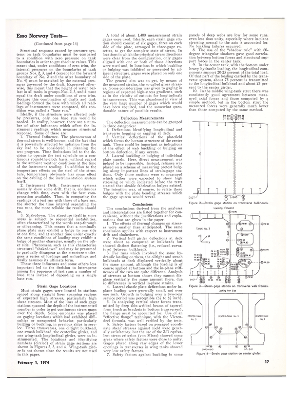
Structural response caused by pressure systems on tank boundaries must be compared to a condition with zero pressure on tank boundaries in order to get absolute values. This meant that, under conditions of zero trim, the internal pressures on the boundaries of tank groups Nos. 2, 3, and 4 (except for the forward boundary of No. 2 and the after boundary of No. 4) must be matched by the external pressures governed by the draft. Expressed otherwise, this meant that the height of water ballast in all tanks in groups Because this combination of drafts and tank loadings formed the base with which all readings of instruments were compared, this condition was called a "base run." Ideally, if the structure were affected only by pressures, only one base run would be needed. In reality, however, there are a number of other influences which affect the instrument readings which measure structural response. Some of these are: 1. Thermal Influence. The phenomenon of thermal stress is well-known, and the fact that it is powerfully affected by radiation from the sky had to be considered in planning the test program. Time limitations led to the decision to operate the test schedule on a continuous round-the-clock basis, without regard to the ambient weather conditions at the time of the instrument reading. In addition to the temperature effects on the steel of the structure, temperature obviously has some effect on the cabling of the instrumentation system itself. 2. Instrument Drift. Instrument systems normally show some drift, that is. continuous change with time, even with the best compensation available. Thus, in comparing the readings of a test run with those of a base run, the shorter the time interval separating the two runs, the more reliable the results should be. 3. Shakedown. The structure itself in some areas is subject to sequential instabilities, often characterized by the words snap-througii or oil-canning. This means that a nominally plane plate may exhibit a bulge to one side at one time, and at another time under exactly the same conditions of loading may exhibit a bulge of another character, usually on the other side. Phenomena such as this characterize structural "shakedown" and may be presumed to gradually disappear as the structure undergoes a series of loadings and unloadings and finally assumes its ultimate form. These three influences and some others less important led to the decision to intersperse among the sequence of test runs a number of base runs instead of depending on a single base run. Strain Gage Locations Most strain gages were located in stations spaced along straight lines spanning regions of expected high stresses, particularly high shear stresses. Most of the lines of such gage stations spanned the depth of the instrumented member in order to get continuous stress maps over the depth. Some emphasis was placed on gaging locations which had exhibited difficulties or unexpected behavior, particularly bulging or buckling, in previous ships in service. Three transverses, one oiltight bulkhead, one swash bulkhead, 'the centerline girder, and one wing-tank longitudinal girder, were so instrumented. The locations and identifying numbers (circled) of strain gage sections are shown in Figures 2, 3, and 4. Wing-tank girder is not shown since the results are not used in this paper. A total of about 1,400 measurement strain gages were used. 'Ideally, each strain gage station should consist of six gages, three on each side of the plate, arranged in three-gage rosettes, to get the complete state of stress. In locations in which the principal stress directions were clear from the configuration, only gages aligned with one or both of those directions were used and, in locations in which buckling or bulging was inhibited or prevented by adjacent structure, gages were placed on only one side of the plate. The general aim was to get, by means of the measured strains, the so-called gross stresses. Some consideration was given to gaging in regions of expected high-stress gradients, such as in the vicinity of cutouts for longitudinals in transverses. This was abandoned in view of the very large number of gages which would have been required, and the somewhat questionable nature of possible results. Deflection Measurements The deflection measurements can be grouped in three categories: 1. Deflections identifying longitudinal and transverse hogging or sagging a't deck. 2. Vertical deflections of the platefield which forms the bottom structure of the center tank. These could be important as indications of the effect of web buckling or bulging on bottom deflection, if any occurs. 3. Lateral buckling or bulging of individual plate panels. Here, direct measurement was judged to be impossible. Instead, reliance was placed on a scheme of measuring pretest bulging along important lines of strain-gage stations. Only those sections were so measured which either were expected to show high stressing or which indicated before the tests started that sizable fabrication bulges existed. The intention was, of course, to relate these bulges with the plate bending stresses which the gage system would reveal. Conclusions The conclusions derived from the analyses and interpretations are listed together for convenience, without the justifications and explanations that are given in the paper. 1. The effects of thermal changes on stresses were smaller than anticipated. The same conclusion applies with respect to instrument drift and shakedown. 2. Vertical hull girder deflections at deck were about as computed at bulkheads but showed distinct flattening (i.e., reduced curvature) between bulkheads. 3. For runs which involved the same hydraulic l-oading on 'them, the oiltight and swash bulkheads at deck displaced vertically about the same amount, although the loading is of course applied at bottom and the in-plane stiffnesses of the two are quite different. Analysis of stresses at bottom shows they cannot displace vertically the same amount there, due to differences in vertical in-plane strains. 4. Lateral elastic plate deflections under inplane loading were generally small, not over one inch. Growth in bulging over a two-year service period was perceptible (j4 to Yz inch). 5. In analyzing vertical shear forces transmitted by deep thin-webbed beams of tapered form (such as brackets in bottom transverses), the flange must be accounted for. Use of an "effective flange" technique, with the Vierendeel formula, was well verified by the tests. 6. Safety factors based on averaged coordinate shear stresses against yield were generally satisfactory, but the use of the 2-D equivalent stress criterion (von Mises) showed some areas where safety factors were close to unity. Gages placed along raw edges of the lower openings in transverses in wing tanks showed very low safety factors. 7. Safety factors against buckling in some panels of deep webs are low for some runs, even less than unity, especially where in-plane stressing normal to the axis is accounted for. No buckling failures occurred. 8. The use of the "shadow rule" with 60- degree triangular shadows gave good correlation between bottom forces and structural support forces in the center tank. 9. In the center tank, with the bottom under heavy hydraulic loading, the longitudinal components support 20-25 percent of the total load. Of that part of the loading carried by the transverse system, about 75 percent is transmitted to the longitudinal bulkhead and about 25 percent to the center girder. 10. In the middle wing-tank strut there was consistently good agreement between measured axial forces and those computed by a simple method, but in the bottom strut the measured forces were generally much lower than those computed by the same method.
Read Esso Norway Test Of Hull Structure Proves Design And Good Workmanship in Pdf, Flash or Html5 edition of February 1974 Maritime Reporter
Other stories from February 1974 issue
Content
- Shipyard Marketing Conference Planned page: 4
- Cordon International To Supply Equipment For Three LNG Ships page: 6
- Sixth VLCC Delivered By Kockums To Salen Features Roller Bearing Design For Shaft page: 7
- Admiral Payne To Succeed Admiral Brockett At Webb page: 7
- NASSCO Launches Largest Vessel Ever Built On West Coast page: 7
- Walter Thorsen, Inc. Named Exclusive Rep For Eleusis Shipyards page: 8
- Ogden Marine, Inc. Buys Two Tankers page: 10
- Oceans International Announces Merger And Expansion Plans page: 10
- Aluminum Tanks And LNG Ship Steel Hulls To Be Joined By Using Du Pont Detacouple Explosion Bonded Welding Transition Joints page: 11
- McAllister Orders Three 4,290-Hp Tugs page: 11
- Delta SS Awards Contract To Equitable For 50 LASH Barges page: 12
- Bethlehem Begins Construction On 265,000-Dwt Tanker —Largest Vessel Built In The United States page: 12
- Arthur Levy Boat Service Announces New Appointments For Thomas And LeBlanc page: 12
- Greek Committee Established By Det norske Veritas page: 13
- Esso Norway Test Of Hull Structure Proves Design And Good Workmanship page: 14
- Todd President Sees U.S. Shipbuilders Improving Competitive Position page: 14
- Society Of Marine Port Engineers N.Y. Discuss Care Of Turbine And Hydraulic Oil Systems page: 14
- Harwich Tonnage, Inc. Formed In California page: 15
- K.W. Waldorf Named To New Zapata Post page: 15
- Bigger, Bigger . . . Bigger page: 18
- USMMA At Kings Point To Admit Women page: 19
- Storm Awards Contract To Bethlehem Beaumont Shipyard For Offshore Drilling Rig page: 20
- NASSCO Expanding Facilities To Build 150,000-Ton Tankers page: 20
- NASSCO Delivers S/S Coronado— First Of Three For Margate Shipping page: 21
- SNAME N.Y. Metropolitan Section Hears Technical Paper On 'New Approach To The Ship Hull Characteristics Problem' page: 21
- ASNE Annual Meeting Set For May 2-3 In Washington, D.C. page: 21
- Experimental LNG Carrier Will Evaluate Two Tank Systems Under Operating Conditions page: 24
- International Ship Suppliers To Meet In Washington, D.C. September 22-26 page: 24
- Thomas B. Crowley Elected President At Western Shipbuilding Ass'n Annual Meeting page: 24
- Whitehouse To Head ABStech Regional Office In Houston page: 25
- Colt Industries Names Nidenberg page: 25
- FMD Appoints Sanchez To Direct Field Operations page: 25
- Alco Engines Names Comeng Holdings Ltd. Australian Licensee page: 25
- Magnavox Announces New Integrated Navigation System page: 28
- Friede & Goldman Inc. Design Zapata Rigs Building At Avondale page: 28
- Sea Trials And Launching Ceremonies Held For AMOCO Tankers At Astilleros Espanoles page: 28
- Halter Delivers New York Pilot Boat page: 29
- Ametco Shipping Elects J.E. Hundt President page: 29
- World Dredging Ass'n New Midwest Chapter To Meet February 28 page: 29
- Wiley And Clyde Iron Now Division Of AMCA Int'l —AMCA Sales $100 Million page: 30
- Kaiser To Build LNG Tanks For Oceangoing Ships On Pinto Island In Mobile Bay page: 30
- Eleusis Shipyards Launches Largest Vessel Built In Greece page: 31
- Paclines To Carry Cargo California To Hawaii Using Tug And Superbarge page: 31
- L. Arthur Strenkert Named Sales Manager Smit Nymegen Corp. page: 31
- Magnavox Announces Offshore Drill Rig Positioning System page: 31
- Paul J. Evanson Appointed Controller Moore And McCormack page: 32
- Paper On Water jet Propulsion Discussed During SNAME Philadelphia Section Meeting page: 32
- Mainland China Places Order Worth $2 Million For Rucker Petroleum Drilling Equipment page: 33
- Pittsburgh-Des Moines Orders Large Quantity Of Aluminum For LNG Ship And Land Use page: 33
- Worthington Service Corp. Names Budrick And lennings page: 33
- Zapata Corporation Reports Record Results page: 33
- Drew Chemical Names Rogers Managing Director New So. Africa Subsidiary page: 33
- Luckenbach To Build New Tampa Terminal page: 33
- SNAME Players Perform At Pacific Northwest Section's 27th Annual Fall Meeting page: 33
- Japanese Firm Buys Lawson Products Corp. —John Gaydos Named page: 34
- David O'Neil To Head New Firm Of Marine Propulsion Consultants page: 34
- Liberian Services —Consulting Firm Elects Wiswall Pres. page: 35
- Diamond M Orders Two Jackup Rigs And A Semisubmersible page: 35
- New Marine Systems Brochure From Waukesha Motor page: 36
- Management Changes At Dearborn-Storm page: 36
- Tanker Management Firm Promotes Nichols page: 36
- DOD Management Of Energy Resources Highlights Naval Engineers Meeting page: 37
- Raytheon Company Submarine Signal Div. Appoints R.G. Popovici page: 38
- Berwind Lines Names Bericochea Exec. VP page: 38
- Selective Calling System Saves Time For Oceangoing Tankers And River Vessels page: 40
- Storehouse Of Information Readily Available From ABS Using Computerized Retrieval page: 42
