Page 72: of Maritime Reporter Magazine (September 1997)
Read this page in Pdf, Flash or Html5 edition of September 1997 Maritime Reporter Magazine
 71
71
 73
73
i
MARINE PROPULSION TECHNOLOGY two outputs of the project: the
Team Process and the Engine
Room Arrangement Models. The 'Team Process' would evolve during the four engine room designs and be documented at the conclusion of the project as the 'Integrated
Product & Process Design User's
Guide.'
Product
As with any technological process, the implementation of
CAD required cooperation, train- ing, understanding and accep- tance.
The prospective users must be willing to modify their paradigms and approach the new technology with an open mind.
There was a huge gap in the way the CAD subteam and the core team wanted to operate. The core team believed that it was "the pri- mary job of the CAD subteam was to prepare drawings," which was contrary to the mission of the CAD subteam, which felt that its prima- ry job was product model develop- ment.
The core team was accustomed to the traditional methods of ship design using paper. It was felt that the development of a 3-D product model was a frivolous activity that detracted from the primary task.
The result was that the CAD sub- team would have to work on the development of drawings as well as the product model.
At this time the CAD team would develop explicit 2-D drawings in order to support the design sched- ule. Through consensus, it was decided that the CAD subteam could develop 3-D models to sup- port product model development, but the drawings must be created on demand in order to support the
ERAM schedule. As time permit- ted, the 3-D product model was developed.
In the beginning the core team communicated the engine room arrangements to the CAD team through the use of hand drawn sketches. The intent was to use these sketches to develop the prod- uct model, which could be used for various analyses including vol- umes and interference detection, as well as to generate documenta- tion including drawings. The ideal approach would have been to gen- erate the drawings from the prod- uct model.
The CAD team had to develop the drawings, but since the model and drawings could not be developed concurrently the CAD team had to temporarily suspend work on the product model. The CAD subteam was tasked to provide blank tem- plates of deck plans and cutouts of equipment. The 2-D plan view deck arrangement drawings were developed using a hybrid approach of incorporating 3-D geometry where it had already been defined.
Equipment, structure and major distributed systems that were not defined were drawn in 2-D. The designers would arrange the cutouts on the plan views, and pro- vide them back to the CAD sub- team to revise the drawings.
Three-dimensional product model development continued by locating these revised 2-D draw- ings in the model and using them as a template to locate 3-D equip- ment. Two-dimensional output was still required to review the design and to convey information to external participants. These sketches were extracted from the product model, and with a minimal amount of cleanup were useful as a j , /
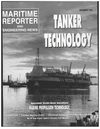
Figure 3 - /
Typical Block Assembly
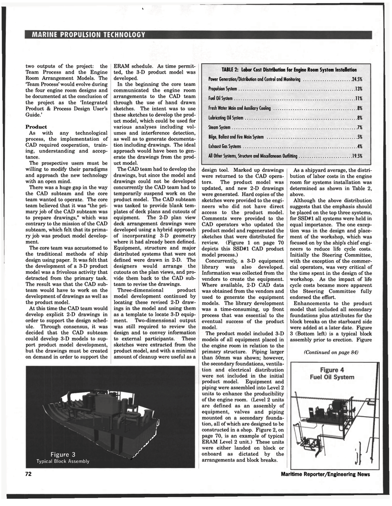
TABLE 2: Labor Cost Distribution for Engine Room System Installation
Power Generation/Distribution and Control and Monitoring 24.5%
Propulsion System 13
Fuel Oil System 11
Fresh Water Main and Auxiliary Cooling 8% lubricating Oil System 8
Steam System 7
Bilge, Ballast and Fire Main System 5%
Exhaust Gas Systems 4
All Other Systems, Strudure and Miscellaneous Outfitting 19.5% design tool. Marked up drawings were returned to the CAD opera- tors. The product model was updated, and new 2-D drawings were generated. Hard copies of the sketches were provided to the engi- neers who did not have direct access to the product model.
Comments were provided to the
CAD operators who updated the product model and regenerated the sketches that were distributed for review. (Figure 1 on page 70 depicts this SSD#1 CAD product model process.)
Concurrently, a 3-D equipment library was also developed.
Information was collected from the vendors to create the equipment.
Where available, 2-D CAD data was obtained from the vendors and used to generate the equipment models. The library development was a time-consuming, up front process that was essential to the eventual success of the product model.
The product model included 3-D models of all equipment placed in the engine room in relation to the primary structure. Piping larger than 50mm was shown; however, the secondary foundations, ventila- tion and electrical distribution were not included in the initial product model. Equipment and piping were assembled into Level 2 units to enhance the producibility of the engine room. (Level 2 units are defined as an assembly of equipment, valves and piping mounted on a secondary founda- tion, all of which are designed to be constructed in a shop. Figure 2, on page 70, is an example of typical
ERAM Level 2 unit.) These units were either landed on block or onboard as dictated by the arrangements and block breaks.
As a shipyard average, the distri- bution of labor costs in the engine room for systems installation was determined as shown in Table 2, above.
Although the above distribution suggests that the emphasis should be placed on the top three systems, for SSD#1 all systems were held in equal importance. The one excep- tion was in the design and place- ment of the workshop, which was focused on by the ship's chief engi- neers to reduce life cycle costs.
Initially the Steering Committee, with the exception of the commer- cial operators, was very critical of the time spent in the design of the workshop. As the impact of life cycle costs became more apparent the Steering Committee fully endorsed the effort.
Enhancements to the product model that included all secondary foundations plus attributes for the block breaks on the starboard side were added at a later date. Figure 3 (Bottom left) is a typical block assembly prior to erection. Figure (Continued on page 84) 72 Maritime Reporter/Engineering News
