Page 25: of Marine News Magazine (August 2005)
Read this page in Pdf, Flash or Html5 edition of August 2005 Marine News Magazine
by Stephen D. Harris, PE
Elliott Bay Design Group
Historically, repairing corrosion dam- age on sizable drydocks has been a time consuming and often costly effort. Emerg- ing technologies have made the job easier and less expensive, while providing a more accurate picture of the issue at hand and offering repair and maintenance feed- back superior to that obtained through conventional practices.
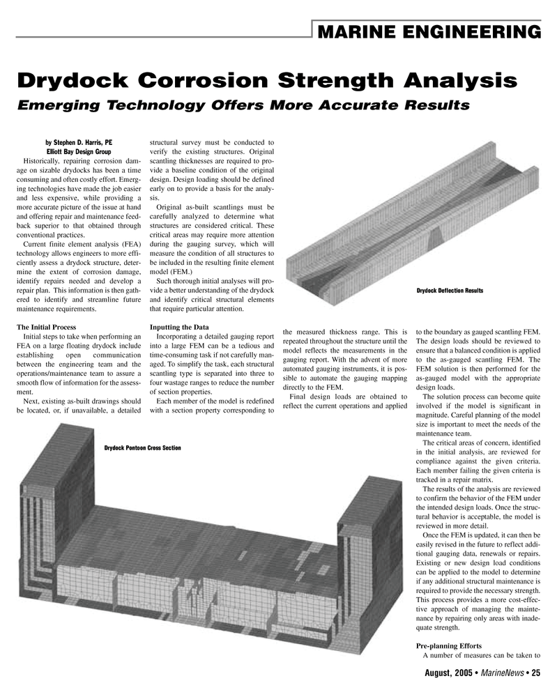
Current finite element analysis (FEA) technology allows engineers to more effi- ciently assess a drydock structure, deter- mine the extent of corrosion damage, identify repairs needed and develop a repair plan. This information is then gath- ered to identify and streamline future maintenance requirements.
The Initial Process
Initial steps to take when performing an
FEA on a large floating drydock include establishing open communication between the engineering team and the operations/maintenance team to assure a smooth flow of information for the assess- ment.
Next, existing as-built drawings should be located, or, if unavailable, a detailed structural survey must be conducted to verify the existing structures. Original scantling thicknesses are required to pro- vide a baseline condition of the original design. Design loading should be defined early on to provide a basis for the analy- sis.
Original as-built scantlings must be carefully analyzed to determine what structures are considered critical. These critical areas may require more attention during the gauging survey, which will measure the condition of all structures to be included in the resulting finite element model (FEM.)
Such thorough initial analyses will pro- vide a better understanding of the drydock and identify critical structural elements that require particular attention.
Inputting the Data
Incorporating a detailed gauging report into a large FEM can be a tedious and time-consuming task if not carefully man- aged. To simplify the task, each structural scantling type is separated into three to four wastage ranges to reduce the number of section properties.
Each member of the model is redefined with a section property corresponding to the measured thickness range. This is repeated throughout the structure until the model reflects the measurements in the gauging report. With the advent of more automated gauging instruments, it is pos- sible to automate the gauging mapping directly to the FEM.
Final design loads are obtained to reflect the current operations and applied to the boundary as gauged scantling FEM.
The design loads should be reviewed to ensure that a balanced condition is applied to the as-gauged scantling FEM. The
FEM solution is then performed for the as-gauged model with the appropriate design loads.
The solution process can become quite involved if the model is significant in magnitude. Careful planning of the model size is important to meet the needs of the maintenance team.
The critical areas of concern, identified in the initial analysis, are reviewed for compliance against the given criteria.
Each member failing the given criteria is tracked in a repair matrix.
The results of the analysis are reviewed to confirm the behavior of the FEM under the intended design loads. Once the struc- tural behavior is acceptable, the model is reviewed in more detail.
Once the FEM is updated, it can then be easily revised in the future to reflect addi- tional gauging data, renewals or repairs.
Existing or new design load conditions can be applied to the model to determine if any additional structural maintenance is required to provide the necessary strength.
This process provides a more cost-effec- tive approach of managing the mainte- nance by repairing only areas with inade- quate strength.
Pre-planning Efforts
A number of measures can be taken to
August, 2005 • MarineNews 25
MARINE ENGINEERING
Drydock Corrosion Strength Analysis
Emerging Technology Offers More Accurate Results
Drydock Deflection Results
Drydock Pontoon Cross Section
AUGUSTMN2005 4(25-32).qxd 8/1/2005 4:44 PM Page 25

 24
24

 26
26
