Contemporary UUV Propulsor Design
From the standpoint of vehicle propulsion physics, an unmanned underwater vehicle (UUV) is little different from your personal ski boat or a tanker. It shares the Vessel-Propulsor-Drive system model, which allows a Propulsor to convert Drive energy into thrust for the purpose of moving a Vessel. The basic principles of thrust equilibrium and motion are common to all three, as are the translation of rotational energy into axial thrust by the central element of the system – the Propulsor.
Not shared by different vehicle types are the constraints and design objectives that are unique to each vehicle’s mission. For example, a ski boat may need high thrust at towing speeds and is willing to give up potential top speed to achieve this mission requirement. Its transmission ratio and propeller characteristics are designed for this purpose. A tanker may need its greatest efficiency at the “speed of business” for the greatest financial return. Or it may additionally have a constraint for emissions or fuel reduction, requiring a compromise in the design of the propeller.
Underwater vehicles have their own set of propulsor design requirements related to their various missions, such as battery life (or greatest distance traveled for the battery budget), maximum body diameter, minimum operational speed, consideration of shrouds or nozzles for hydrodynamic efficiency or safety from propeller contact, or reduction of noise to ensure quiet operation for data gathering. This is the setting for our UUV propulsor design work at HydroComp, and it starts with a client interview to glean the really important information for a successful design project. The Vessel-Propulsor-Drive model is a good framework for such discussions.
Vessel
The typical UUV is a body-of-revolution hull form (also called an axi-symmetric form) that has a nose, body, and tail. For the sake of maximum internal volume for equipment, some vehicles have a very short nose and tail. As you might expect, there is a certain drag penalty for a blunt nose and a propulsion penalty for flow into the propulsor that is not axial but along a steep slope. Part of our work is to balance the different part of resistance – wave-making or pressure drag versus the frictional or viscous drag – to get the least resistance-to-volume outcome. Actually, that’s not completely true. We really want a least power-to-volume outcome, and the tail geometry will greatly influence a propulsor’s ability to develop useful axial thrust from the rotational energy.
Therefore, many propulsor design projects start with prediction of a vehicle’s drag and hull-propulsor coefficients (wake fraction and thrust deduction) using the NavCad® software for hydrodynamic and propulsion system simulation. A specific submersible vehicle module provides robust prediction capabilities for torpedo-like UUV hull forms.
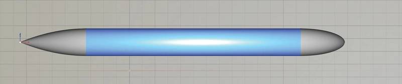 Image: HydrocompDrive
On the other side of the Propulsor is the Drive, which will typically be an electric motor. Motors vary in electrical characteristics, but the critical data for propulsor design are its mechanical output power-RPM curve at the shaft. The “upstream” electrical input power is important, of course, and provides an operational constraint. We characterize the input electrical power with the motor efficiency curve, which helps answer the question: what is our optimum target RPM range if greatest battery life is the highest priority? On the other hand, it is the shaft’s power-RPM curve that tells us the RPM for the maximum possible shaft power and, by extension, the RPM for maximum potential propulsor thrust and vehicle speed.
As you can see from the representative motor curves of shaft power and electrical efficiency versus RPM, the highest potential power rarely (if ever) occurs at the highest electrical input efficiency. So, we often have to define the RPM design point as a compromise that gives neither the higher power output nor the best electrical efficiency.
Also relevant to any discussion about motor-driven UUVs is that shaft RPMs are almost always substantially too high for optimum propulsor operation. It is not uncommon to see some form of gearing to achieve best propulsor performance – or to accept that the propulsor may be operating with mediocre efficiency.
Propulsor
You will note the use of the term “propulsor” rather than “propeller”. This is to reinforce the concept that a nozzle and propeller (as found on most UUVs and often called the vehicle’s “thruster”) is an interactive unit, the Propulsor. Propulsor design is a combination of finding the best propeller and nozzle (also called duct or shroud) while keeping track of their interaction. In other words, you must use design tools that include this interaction, such as NavCad for system modeling or PropElements® for propeller-nozzle component design.
In all UUV propulsor design projects, one universal objective is to develop a geometry that generates the highest thrust-to-power ratio (its efficiency), which we achieve using well-established practices. It is generally the influence of external design drivers that can make successful UUV propulsor design so challenging. For example, the RPM can be too high (as noted above). Geometric constraints can limit the maximum diameter (to ensure it remains within the body diameter) or they can influence the design to account for slope of the vehicle’s tail.
It is important to take a moment and mention the implications of UUV propulsor manufacture. There is substantial discussion in the press about additive manufacturing (AM) for propellers. While this may be attractive from a financial and deliverability standpoint, we must take care that performance is not compromised by inappropriate surface texture (which can have a huge influence for propulsor of the small size found on most UUVs), fatigue strength failures, or by hydro-elastic flexure in the blade. HydroComp has developed successful practices for the use of AM for small propulsors through a variety of in-house research projects.
Beyond these practical design considerations, one of the most interesting contemporary design drivers the topic of radiated noise. As part of a broader sustainability initiative, HydroComp has developed expertise in the prediction and mitigation of propulsor hydroacoustics (the term that captures noise and vibration). This knowledge is also being made available to other naval architects and engineers as new hydro-acoustic features are developed for our tools. A project’s sensitivity to noise is now always part of discussion with our UUV propulsor design engineering clients.
All hydroacoustic excitation is from mass fluctuation (the periodic movement of fluid mass). Propulsor-driven hydroacoustics is generally caused by variations in the low-pressure zones of the propeller as it rotates in-and-out of “shadowed” regions, such as behind a strut or control fin. Part of the fluctuation is simply from the change in flow direction around the blade caused by the varying inflow, but more significantly by the rapid expansion and collapse of cavitation on the blade. Each of these is evaluated as part of our propulsor design, with mitigation as needed by changes to a blade’s outline and its camber-pitch distribution.
Excessive hydroacoustic excitation – and transmission – can also be aided with a creative nozzle design. Using our background in nozzle performance modeling, we can consider if particular noise-quieting nozzle geometry can offer the necessary suppression, as well as any loss of propulsor efficiency.
So, while UUV propulsor design has its collection of unique challenges, is it still just a component task within a larger system problem. It can offer a satisfying engineering challenge, one that can be successfully completed with a little care, proper tools, and practical experience.
About The Author
 Donald MacPherson, the author.
Donald MacPherson, a leading specialist in propulsion system simulation, is HydroComp’s Technical Director, where he oversees all software development and engineering services. A graduate of Webb Institute, he is a Fellow of SNAME and member of its Propulsion Hydrodynamics Panel.

Read Contemporary UUV Propulsor Design in Pdf, Flash or Html5 edition of January 2019 Marine Technology
Other stories from January 2019 issue
Content
- Subsea Electrification: Subsea Power Evolves page: 16
- Contemporary UUV Propulsor Design page: 20
- Unmanned Vehicles: 25 Years of Milestones page: 26
- Subsea: The Future of Unmanned Vehicles page: 34
- The “Disruption” in AUV Trends page: 42