
Thruster Design for Submersible Developers
Many companies involved in submersible vehicle development also look to equip the vehicle with a custom thruster. These companies typically have expertise in vehicle and drive design, but will not be experienced in propulsor design. Nor would they be expected to have the specialized tools necessary for proficient thruster design, analysis, and optimization. This article will introduce submersible vehicle developers to the design practices used by HydroComp and other specialists to deliver thruster designs that are among the highest thrust-to-power ratio propulsors in service.
PROPULSOR DESIGN OBJECTIVES
The ultimate objective of thruster design for vehicle development is typically a 3D CAD model of the propeller and nozzle that will support – and enhance – the technical and business mission of the vehicle. Three principal task groups make up a complete thruster design project – Vehicle-Propulsor-Drive system matching, thruster component optimization, and geometric modeling.
Vehicle-Propulsor-Drive system matching
This initial work package will determine the principal propeller and nozzle characteristics that are properly “matched to the system”. Critical to the overall success of the thruster design process is to first determine the appropriate principal specifications of the propulsor and drive system, and only then can the propeller and nozzle components be designed in detail. Propulsor specifications that are determined during system design are typically: configuration (open vs. ducted), nozzle style (as needed), blade count, diameter, pitch, and blade area ratio. Critical drive parameters (that are simultaneously determined) are mechanical shaft power (not electrical power), RPM, and position of the design point on the drive’s shaft power curve (such as using the electric motor performance curves to balance performance versus battery life, for example).
Thruster component optimization
This task group provides hydrodynamically-optimized propeller geometry (within the selected nozzle type) that is “designed for performance” for the particular vehicle’s hydrodynamic properties and its interaction with the propulsor. After the principal system characteristics of the propeller and drive are defined in the prior stage, the details of the propeller component can then be designed. This process, called “wake-adapted propeller design”, delivers the radial shape parameters that reflect size (chord, thickness, foil), lift (pitch, camber), and position (rake, skew). These parameters are designed to a specified vehicle speed, required thrust loading, and shaft RPM (i.e., the “design point”), with supporting evaluations for cavitation and blade strength.
A multi-duty application (such as an adaptive UUV that will carry both roles of transit AUV and workhorse ROV) might require a balanced perspective for a “compromise” design. As performance objectives change, so will the optimum characteristics of the propeller – and its nozzle. Multi-mode optimization is not difficult; it just needs some care to review the designs in the context of the total mission requirements. In many cases, a weighted calculation of overall duty-profile power demands can illuminate any problems meeting the necessary performance requirements within the expected “energy budget”.
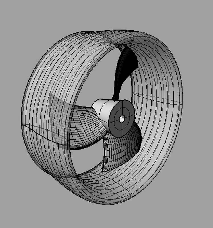 Image: HydrocompGeometric modeling
A full “designed for manufacture” 3D CAD model is then developed and delivered for prototype testing and deployment. Given the geometric parameters determined in the wake-adapted optimizing design stage, a full blade shape is generated. The blades must then be incorporated with a hub (that can have many different types of shaft attachments), with fillets and other details added during a 3D CAD process. There may also be additional considerations for specific manufacturing processes that will affect the shape, such as casting or milling. Development of the nozzle’s geometry is really little more than an annular (rotational) extrusion of a suitable foil profile.
REQUIRED TOOLS FOR PROPULSOR DESIGN
A typical thruster designer’s workbench will include the following software tools. A list of necessary tool functions and features are shown for each of the three principal design tasks.
Tools for Vehicle-Propulsor-Drive system matching will be built upon an optimizing solver that can determine propeller characteristics for maximum efficiency while considering any constraints for configuration, maximum propeller diameter, and cavitation limits. This must include both Thrust-based and Power-based loading options to handle transit and towpull mission roles. Suitable propulsor prediction models must be included for the propeller and nozzle styles under consideration. Finally, the performance of the optimized propulsor must be evaluated with the vehicle and drive, including prediction of the operating RPM and the required power.
Tools for thruster component optimization will typically be a blade-element calculation for the propeller, with support for various styles of nozzles and shrouds. CFD and other such codes may be used, although propeller-specific wake-adapted design tools can offer a variety of technical, financial, and workflow benefits. These including a structured “extruded foil” framework for management of the design parameters, automatic solution of optimum pitch and camber for the design objective, and the ability to alter radial loading as needed for supplemental design issues (such as for consideration of hydroacoustics, root cavitation, or strength, for example). Propeller-specific design tools also offer assessment of critical cavitation metrics (with feedback for design), and evaluation of blade strength and safety factor for various material properties.
Necessary for geometric modeling would include a tool with specific capabilities for propeller blade design, augmented with general-purpose CAD/CAM software for the less geometrically challenging roles (including nozzle shape development). Blade shape creation is very challenging for general-purpose CAD tools, so a propeller-specific tool for geometric blade design can offer mathematical functions for blade shape creation, including a library of contemporary and traditional propeller section shapes. Of course, export to general-purpose CAD/CAM is necessary for completion of the 3D CAD model (with the generated blades and hub).
REQUIRED EXPERTISE FOR IN-HOUSE THRUSTER DESIGN
Competent thruster design does require an understanding of the principles of propulsion system interaction, propulsor performance, and propeller-nozzle geometry. That being said, it does not necessarily require a degree in naval architecture or hydrodynamics. For example, a mechanical engineer with a university course in fluids can easily develop the additional skills needed for successful thruster design. Used by nearly 200 propulsor designers and manufacturers around the world, HydroComp’s suite of tools (NavCad, PropExpert, PropElements, and PropCad) provide a comfortable framework that lends itself to a “guided workflow”, allowing in-house design to be both practical and cost-effective.
PARTNERING WITH A SPECIALIST
Of course, not everyone wants or needs to have propulsor design capabilities in-house. In those cases, reaching out to a specialist with appropriate knowledge, experience, and resume’ of successful projects can indeed make sense. If this sounds like you, we would be happy to discuss your project and thruster design requirements.
Read Thruster Design for Submersible Developers in Pdf, Flash or Html5 edition of July 2019 Marine Technology