Page 7: of Maritime Reporter Magazine (June 1971)
Read this page in Pdf, Flash or Html5 edition of June 1971 Maritime Reporter Magazine
 6
6
 8
8
GTS Euroliner (Continued from page 7) ment, cargo capability, manning and ship availability must all be consid- ered.
The compact, modular design of the Power Pacs permit significant shipyard installation labor economies and total savings in ship cost of 10 to 15 percent. The ease of automation permits unattended engine room op- eration with substantial savings in manning. In a volume limited hull such as a container vessel, the 10 percent additional cargo capability is very significant. Of most importance is the reduced off-hire time to be expected as a result of high engine reliability and the six hour engine change-out capability for overhaul.
This, of course, permits tighter sched- uling and annually a much more pro- ductive vessel.
Turbo-Power and Marine Systems,
Inc. (TP&MS) have had the re- sponsibility for providing the prime movers, marine propulsion control system and acting as advisor for the entire propulsion train, duct work and other related components. For- merly a department of Pratt & Whit- ney Aircraft, TP&MS was newly established as a separate subsidiary of United Aircraft Corporation in 1970.
Two FT4A-12 gas turbines pro- vide a total of 60,000 bhp for Euro- liner's top speed which is well in ex- cess of 27 knots. The ship has also demonstrated her capability of 21 knots on one shaft.
The FT4A-12 gas turbine was de- veloped from the J75 aircraft jet en- gine which powers the Boeing 707 and DC8. Extensive changes were accomplished to make it suitable to the marine environment. In its pres- ent marine form the FT4A-12 con- sists of two major components, the gas generator and the free turbine.
The gas generator consists of a low- and high-pressure compressor section, a combustion section, and turbines to drive the compressors. The eight-stage low-pressure com- pressor and the seven-stage high- pressure compressor are driven by a two-stage and a single-stage turbine, respectively. Between the compres- sors and turbines is the combustion section consisting of eight combustion chambers arranged around the shaft, with each combustion chamber hav- ing six fuel nozzles.
The hot gasses from the gas gener- ator are used to rotate the free tur- bine which is a two-stage reaction turbine. The operating speed of the free turbine is 3,600 rpm which is lower than many steam turbines and, therefore, simplifies the reduction gear requirements.
To assist shipyard installation of the FT4 and to insure optimum de- sign, the Power Pac approach was taken for Euroliner. A power module was conceived which would permit "plugging in" the power source. In addition, the dimensions of the mod- ule or Power Pac were to be such that shipment in a 40-foot container would be feasible. Also, the con- tainer would serve as a store house for the shipyard until the Power Pac was installed in the ship. As such, the container was fitted out with lighting, dehumidification equipment and tool storage.
Each of the two FT4 Marine Pow- er Pacs in Euroliner are approxi- mately 27 feet long and 8 feet wide with a total weight of 15 tons.
Only about half of the weight is at- tributed to the engine, with the re- mainder being such items as the foun- dation, supports, enclosure and addi- tional support equipment. The engine enclosure provides both sound isola- tion and proper engine cooling. To facilitate engine maintenance, doors on either side provide for easy access.
In addition, the roof of the enclosure is easily removed when changing the engine for overhaul. Included within the Power Pac are the complete lu- brication systems (with coolers and precipitron), fire detection and pre- vention equipment plus all necessary electrical cables and piping for the starting and ignition systems.
All necessary connections are ter- minated at the base for quick and simple coupling of cables and piping by the shipyard. Actual installation within a ship, including the initial alignment, can be accomplished in one week.
The main components of the two propulsion trains consist of conven- tional marine, double-reduction, lock- ed-train reduction gears and variable- pitch propellers. The variable-pitch propellers were manufactured by
LIPS in Holland and provide for maximum operational flexibility. The reduction gears were provided by
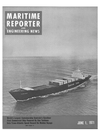
DeSchelde and, due to the high torque (Continued on page 11) Stern view of the superstructure shows the engine air-intake enclosures on aft side
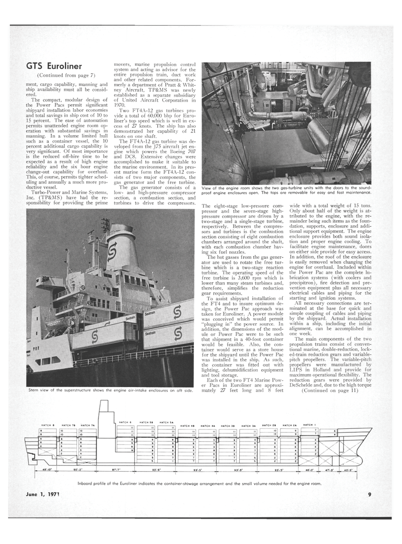
View of the engine room shows the two gas-turbine units with the doors to the sound- proof engine enclosures open. The tops are removable for easy and fast maintenance
June 1, 1971 9
