
Page 14: of Maritime Reporter Magazine (June 15, 1973)
Read this page in Pdf, Flash or Html5 edition of June 15, 1973 Maritime Reporter Magazine
 13
13
 15
15
Sun Shipbuilding Reports On Experience With
Computers In The Design Department
To Control Shipboard Interferences
J.K. McNeal, R.P. Kakad and J.S. Magrie*
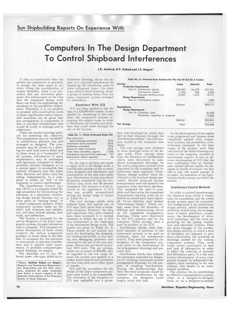
Table No. 2—Prorated Cost Analysis For The Use Of ICS On A Tanker
Savings
Production Departments
Due to: Interference reports
Interference checks
Reduced drafting errors
Design Departments
Due to: Interference checks
Expenditures
Design Departments
Due to: Computer costs
Manpower, inputting to computer
Labor $32,952 2,354 13,497
Subtotal
Net Savings
Subtotal
Total
Material $4,279 305 1,274
Total $37,231 2,659 14,771 1,050 $55,711 $7,035 15,026 $22,061 $33,650
A ship as constructed does not permit one component to physical- ly occupy the same space as an- other. Given the consideration of human fallibility, there is no pro- cedure that can absolutely guar- antee this achievement at the time that the completed design work flows out from the engineering de- partment to the production depart- ment. Therefore, it is not prudent to proceed with construction work of major significance until a reason- able assurance can be given that any arrangement of components is free of physical interferences that would be costly to redesign and to refabricate.
There are several existing meth- ods for achieving this objective.
The components may be "modeled" in scaled-down physical size and arranged as designed. The com- ponents may be shown on a draw- ing for each local area in detail and in three views, in a "composite" of all systems. Information of space requirements may be exchanged and rigorously compared to detect problems 'between designers or to a central agent to accomplish this method. Designers may also input their decisions and plans, each one acting independently, to a com- puter to obtain the "aid" of the computer to control interferences.
The Interference Control Sys- tem (ICS) is a computer-aided de- sign procedure for determining the existence of a physically interfer- ing design layout between two or more parts or "catalog items" of a ship's component systems. These component systems make up the ship's hull structure and machin- ery, and they include piping, duct work, and calbleways.
The System is arranged for the use by designers of the ship's com- ponent systems through interaction with a computer. The computer re- ceives descriptions of items which, comprise the various component systems; it stores them in the data files. It computes for the existence or occurrence of physical interfer- ence and it reports such occur- rences. It produces computer-gen- erated drawings on request.
The drawings are of two dif- ferent types: one type, called an in- *Messrs. McNeal, Kakad and Magrie,
Research and Development Department,
Sun Shipbuilding and Dry Dock Com- pany, presented the paper condensed here before a recent meeting of the
Delaware Valley Section of the American
Society of Naval Engineers. ter fere nee drawing, shows the na- ture of a reported interference by displaying the interfering parts in three orthogonal views; the other type, called a detail drawing, shows a group of catalog items from the same component system arranged for fabrication.
Experience With ICS
ICS has been applied to the de- sign of a 126,000-dwt tanker. It was applied by simulating in the com- puter the component systems oc- cupying the engine room in order to determine the benefits and prob- lems that could result through the use of the System.
Table No. 1—Work Performed Under ICS
Pipe items and detail drawings simulated 55%
Ventilation ducts simulated 20%
Cableways simulated 70
Structural items simulated 30%
Total items simulated, approx. 7,000
Interference reported (from drawings) 1 37
Interference checks reported 42
By the time a decision was made to apply ICS to the design work, a considerable nunvl>er of the systems were designed and fabricated, and construction of the ship was under way. Fabrication of pipe was about 60 percent completed, and the ven- tilation duct work was 90 percent templated. The amount of work in- volved in the application of ICS that was actually accomplished during the design stage is shown in Table No. 1.
The cost savings which were realized from this partial use of
ICS were little more than a break- even situation. However, the data and experience that were realized have been prorated to a normal situation in which the use of ICS was commenced at the beginning of the mechanical design work. The results are given in Table No. 2.
These results do not include any costs for developing the program, for training personnel, or any test- ing and debugging problems that occurred in the use of the new pro- gram. These costs are based on cur- rent 1973 rates. The net savings, which are in excess of $30,000, may be regarded as the low range be- cause the system was applied to a tanker where interference problems are less than with most other types of vessels.
ICS and the procedures for the design of the ship's component sys- tems were found to 'be compatible.
The resistance of the designers to
ICS was negligible and a proce- dure was developed by which they had at their disposal, through the "interference checks," the informa- tion stored in the computer data banks.
The cost savings were obtained in three principal areas of the de- sign work. First, savings came from the detection of interferences which were discovered in com- pleted arrangement drawings. As the ship's component systems were simulated in the computer and in- terferences were reported, "inter- ference change notices" were dis- tributed to the involved design per- sonnel. Second, proposed system arrangements were simulated in the computer from free-hand sketches.
This mitigated the need to com- plete and then revise the completed arrangement drawing when an in- terference would have been report- ed. Those sketches were termed "interference checks." Third, sav- ings came from the discovery of drafting and dimensioning errors on the completed arrangement drawings. These were discovered by the ICS operator and by the computer. These savings were a pure by-product of the ICS.
Interference checks were free- hand sketches of portions of the component systems to be used as computer input for interference control. They were prepared by the designers of the component sys- tems prior to the development of the arrangement drawings and ma- terial lists.
Interference checks also reduced the manhours expended by design- ers for studying component system arrangement drawings for the pur- pose of avoiding interferences.
Having the foreknowledge that their free-hand proposals would be checked for interferences by the computer, the designers could largely avoid this task.
As the development of the engine room progressed and became more completely packed with compo- nent systems, the probability of in- terference increased. In the later stages of the project, more than one-third of the detail drawings en- tered to the computer resulted in interference reports. It was an ob- vious shortcoming of ICS that the bare notification that an interfer- ence existed did not enable the de- signer to rectify it without the fear that a new one would emerge in its place. An extension of the inter- ference-check concept provided the answer.
Interference Control Methods
In order to control interferences, the situation from which it results must be considered, and the entire design process must be evaluated.
The background is the preliminary design activity, which includes the definition of hull form, the arrange- ment of major machinery compo- nents, the development of struc- tural scantlings, and the basic en- gineering for the piping, ventila- tion, and electrical systems. Then the scene changes to the produc- tion design activity, in which a host of designers are released to pro- duce concurrently the hundreds of drawings needed for the various component systems. They work under severe constraints of time and lack of information in order to effect the ordering of material and fabrication parts. It is the con- current development of many com- ponent systems by independent de- signers, each operating in his own vacuum, that results in an inter- ference problem.
The solution lies in establishing an effective communication system, either on a designer-to-designer basis, or on a designer-to-central 16 Maritime Reporter/Engineering News
