
Page 15: of Maritime Reporter Magazine (June 15, 1973)
Read this page in Pdf, Flash or Html5 edition of June 15, 1973 Maritime Reporter Magazine
 14
14
 16
16
agency (basis. Infra-drawing room communication is an integral part of the production design activity, and it can greatly reduce the num- ber of interferences. However, the number still resulting makes a sup- plementary program of centralized interference control very attractive.
At least three methods of cen- tralized interference control have been tried: 1. physical models; 2. composite drawings, and 3. com- puter simulation.
Some of the characteristics as- sociated with these methods are summarized in Table No. 3. "Time- liness" refers to the time delay be- tween the completion of drawing of a component system and the re- port of its interference status. For significant savings to be realized, potential interferences must be de- tected and rectified before work is initiated by the production depart- ments. It was primarily a deficiency in this characteristic for both com- posite drawings and physical mod- els that fostered interest in com- puter simulation. The timeliness for ICS given in Table No. 3 as- sumes that one person prepares the computer input for 10 designers.
Accuracy and readability char- acteristics refer to the susceptibili- ty for error that derives from the use of the method. After composite drawings have been modified many times, they become complex, con- gested, and smeared; therefore, they are susceptible to misinterpre- tation. Physical models have prob- lems with accuracy from working with plastic and glue. Deviations from true dimensions are multi- plied aboard the ship by the scale factor (usually 10 to 1). The com- puter simulation data are stored in the computer to an arbitrary precision. For ICS, the accuracy is plus or minus one-eighth of an inch. "By-products" are the benefits derived from an interference con- control methods varies as follows for a comparable 126,000-dwt tank- er :
Composite drawings ... $ 25,000
Physical models $125,000
Computer simulation . . $ 25,000
For this outlay, the return in the form of cost savings has been esti- mated. Consideration has been giv- en for any savings due to by-prod- ucts. The result is given in Table
No. 3 as "ratio of return to out- lay."
Further Possibilities And Benefits
The Interference Control Sys- tem can be extended and modified easily to obtain other functions, such as isometric and orthogonal view arrangement drawings, ma- terial lists, weight and moment calculations, composite drawings, and cut and bend lists for piping.
The Ship and Catalog Files may be accessed by separate, additional programs as a basis for further de- velopments.
Locations of the various compo- nent systems in a ship (piping, ventilation ducts, structure, ma- chinery, etc.) have been determined and stored in the ship file. Both isometric and orthogonal views of arrangement drawings could be generated by modifying the ICS.
The Ship File contains all the data needed to produce bills of ma- terials. The ICS can be extended to produce bills of materials for any particular component system in the ship. For example, the main steam supply system can be ana- lyzed by the computer to give total lineal feet of pipe. It can give the number and specification of valves and all other pipe fittings. By add- ing the corresponding weights of items, the ICS might be extended to give weight and moment calcu- lations directly, which would be related to the geometric descrip- tion of the items in terms of the basic shapes comprising them.
Table No. 3—Characteristics Of Interference Control Methods
Composite Physical Computer
Drawings Models Simulation (ICS)
Timeliness 4 to 6 weeks 2 to 8 weeks 0.5 weeks
Accuracy & Legibility poor fair very good
Designer Efficiency fair fair good
By-Products none designer's aid detail plans rigging interference training plots
Ratio of Return to Outlay 100% 75% 250%
Basis for Further Development poor poor very good trol method, beyond interference control itself. These benefits gen- erally do not require appreciable additional investment of time or capital. The three-dimensional phy- sical model enables designers to grasp otherwise obscure character- istics of the engine-room arrange- ment and, consequently, to devel- op optimum component systems.
The most efficient sequence of crane lifts for the assemblies that comprise the engine room may be more easily determined by the rig- gers via inspection of models. Per- sonnel training is also more readi- ly accomplished through the use of models.
The approximate cost outlay re- quired to implement interference
The ICS can be extended to gen- erate cut and bend lists to pro- vide dimensions and optimized se- quences for fabricating piping as- semblies. The program can ulti- mately foe used to output tapes to run numerically controlled ma- chines for cutting and bending pipes in fabricating piping assem- blies.
The principal benefits of the ICS may be summarized as savings in cost, both in design and in fabrica- tion. While it is alleged that signi- ficant cost savings might be ob- tained (having been estimated as a return of $2.50 for every $1.00 expended on ICS), there is a fur- ther extension that might ultimate- ly produce an optimization result- ing in an increase in payload or the revenue-earning capacity for the ship. This benefit stems from a two-part extension: first, into "routing" of the distributive sys- tems, and secondly, into "arrang- ing" the engine-room space. The first step is a necessary capability before the second can be realized.
The result would simulate an optimum arrangement and location of important equipment in the ship and then route the various compo- nent distributive systems to con- nect this equipment. This would re- sult in interference-free routing and optimal arrangement of all com- ponent systems in the ship. This could be converted into reduced machinery space and increased availability of cargo space for a given design.
Basic Program Structure
The ICS programs control the computation (of interference) within the computer. They consist of two main programs. The first program (called 635 EXEC) con- trols processing on a GE 635 or
Univac 1108 Computing System for making calculations as well as pro- ducing data for further processing by the second program. The 635
EXEC program with 125 subpro- grams performs the data file and interference computing activities.
These subprograms are written in full Fortran, except for the six sub- programs concerned with data files and written in assembly language.
The 635 EXEC program performs its work using eight basic functions that comprise eight of the subpro- grams and which make use of the remaining 117 subroutines and sub- ordinate functions.
The second program (called 1130
EXEC) controls processing on an
IB'M 1130'Computing System with an attached Genber 522 Drafting
System for making drawings. The program can also drive an attached
Calcomp 663 Plotter. The input data comes from the first program and determines whether the pro- gram will produce an interference drawing or a detail drawing. The program is written in basic For- tran and performs the single func- tion of making drawings.
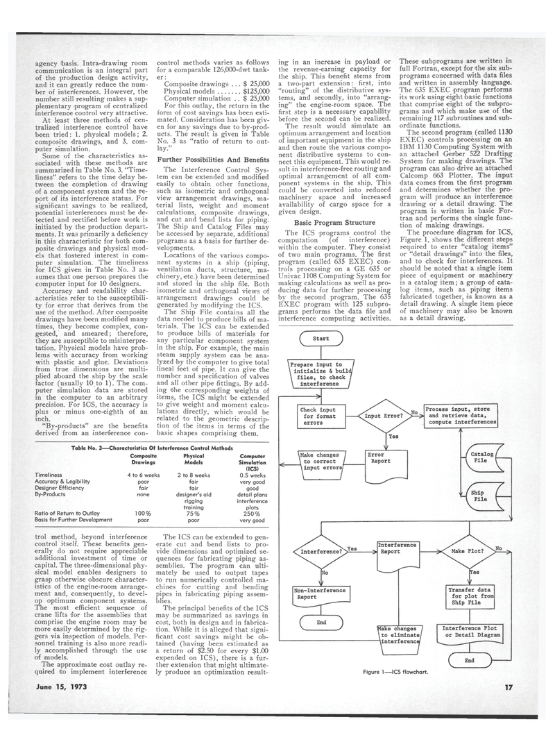
The procedure diagram for ICS,
Figure 1, shows the different steps required to enter "catalog items" or "detail drawings" into the files, and to check for interferences. It should be noted that a single item piece of equipment or machinery is a catalog item; a group of cata- log items, such as piping items fabricated together, is known as a detail drawing. A single item piece of machinery may also be known as a detail drawing. c Start \Prepare input to initialize & build files, to check interference
Check input for format errors \Make changes to correct i input errors.
Process input, store and retrieve data, compute interferences
Non-interference
Report
Q End ^
Make changes 1 \to eliminate/ -^interference/
Figure 1—ICS flowchart.
Transfer data for plot from
Ship File
Interference Plot or Detail Diagram
June 15, 1973 17
