
Page 13: of Maritime Reporter Magazine (September 1974)
Read this page in Pdf, Flash or Html5 edition of September 1974 Maritime Reporter Magazine
 12
12
 14
14
Numerical Control- assembly containing a series of se- quential isometric sketches show- ing welding details. These booklets can list what parts are to be coded for N/C tapes or 1:10 scale and 1:1 templates or simply laid off in the fabrication shop.
Breaking down the subassem- bly into sequential steps also assists the planning department to determine the work content and each craft can easily retrieve the information they require.
Every operation presently utiliz- ing detailed structural drawings can be significantly clarified and simplified with significant savings resulting from such an approach and the time required to complete all the details, information, and booklets reduced to at least half of what is normally required.
This, in turn, will allow the plan- ning department to complete its detailed analysis earlier in the production cycle.
Unfortunately, all this time saving is not necessarily available as a total building-time savings due to the fact that as the time to complete the structural part of engineering and planning is re- duced, other engineering aspects or the procurement of material become the critical item. How- ever, the use of computer-aided programming systems usually al- lows a better engineering job to be done.
Programming Group
The main function of a N/C programming group is to provide all required N/C tapes, N/C draw- ings, 1:10 templates and related information to the production de- partment for processing all the structural material required to build a ship.
The responsibilities of the N/C programming group will obviously depend on the individual shipyard organization requirements. How- ever, it is considered essential for the greatest success of the sys- tem that the existing steel draw- ing office and the N/C program- ming group be integrated into one structural-work preparation de- partment. Such a department could be completely responsible for the preparation of all infor- mation that the production de- partment requires to build the structural part of a ship.
They also would be responsible for structural-material lists and the preparation of N/C drawings for other departments. If the de- partment is given such respon- sibility, it must obviously be given the authority necessary to accept the responsibility.
The proposed structural-work- preparation department could be organized as shown in Figure 2.
It is split into two sections, but their operations are very closely intertwined and, therefore, are under the control of a department head who reports directly to the vice president-technical.
September 1, 1974
Table 1—Manning Requirements for N/C Data-Processing Section
A. Annual forecast of ship type and size
No. Type LBP Manhours
Preparation
Period (Weeks) 1 Tanker 2 Bulk Carrier 1,000 800 24,000 24,000 25 25
Total 48,000 50
Required total number of staff = 24
B. Manpower Disposition
Manhours
Number of
Personnel
Fairing
Sight-edge fairing
Longitudinal fairing
Shell development
Assembly jig tables
Norm writing
Frame & long'l bending
Scientific calculation 1V2% y2% 3A% 2y2% 1%% 2% 2 Vt% l3/4% 720 240 320 1,200 800 960 1,080 800
Sub-Total 6,120 3
Part generation
Nesting 25% 20% 12,000 3,600
Sub-Total 21,720 11
Validation & liaison
Supervision 30% 12% 14,400 6,000 7 3
Grand Total 100% 42,120 24
Skills and Training
Most existing computer-aided lofting systems are production- oriented and basically replace a function which was previously all manual by a combined computer- manual operation. From this point of view, the skills required by personnel who will use the com- puter-aided lofting system are almost the same as for the pure manual system. The only signifi- cant difference being that draft- ing or layout lose their impor- tance. Obviously, the users must be able to work with numerical data and have a good knowledge of at least elementary trigon- ometry.
In this country, many of the early users of computer-aided ship lofting systems were re- cruited from the aircraft and industrial N/C fields, but their effectiveness was restricted due to their lack of shipbuilding ex- perience. The average shipyard draftsman or loftsman can learn the basics of coding in three to four weeks and become quite pro- ficient in the use of the system in less than a year, whereas it takes many years to learn the many facits of shipbuilding that the shipyard draftsmen or loftsmen require to do their job.
Assuming a staff of three sys- tems analysts and 12 users, the training requires an investment of over 100 manweeks or approxi- mately $50,000. Add to this the cost of the instructors and com- puter usage, the investment can be $100,000.
Future Developments
It is obvious to anyone working with N/C that the present state- of-the-art is just scratching the surface of the potential use of the computer in all phases of ship production. Therefore, the basic need for the future is to continue the effort to expand the applica- tion of N/C to shipyard methods and to better integrate the pro- cesses involved from design through production.
The present state of capabilities allows access to the following types of information for the hull structure: area of parts, perim- eter of parts, thickness and weight of parts, position of parts in ship coordinates, and position of parts on nested formats.
The immediate future should see the following type of pro- grams implemented in connection with N/C: 1. Interference program for dis- tributed systems and compart- ment equipment. 2. Automated bill of material for: hull structure, piping sys- tems, and ventilation systems. 3. Pipe design and sketching, and N/C pipe bending and finish- ing systems. 4. Increased use of computer graphics for input of required information.
Contract General Arr.
Contract Lines Plan
Contract Structural Plans
DESIGN &
ENGINEERI'.
Preparation of Struc tural Drawings for
CIassi fi cation
Society Approval .STRUCTURAL [PRODUCTION
ENGINEERING
N/C DATA
PROCESSING (PROJECT
PLANNING | DETAILED
PRODUCTION
IMATERIAL
I
Preparation of Mas- ter Erection & Weld-_ ing Sequence Booklet
Fai ri ng of Hul1,
J Shell Sight Edges, becks & Longitudinals ! 1 r i W |
Preparation of As- sembly & Welding Se- quence Booklets,incl
Part Identification i . i
Shell Development -and Material Listing | 4 ' r 1 ? I r i
Structural Material
Ordered
Weights and Areas to Design
Parts generation &
Nesting, includinq listing of nested piates, weights area & production data
Project Planning and Scheduling of
Work and Material
PLANNING &
CONTROL •
Validation of tapes & N/C drawings and preparation of al 1 other Loft-type info.
Detail Planning and
Preparation & issue of work orders, incl budgets, resource allocation, material routing and all othe required production information.
Expediting structur al material delivery and allocation in stockyard.
T STRUCTURAL PROCESSING
FABRICATION & ERECTION
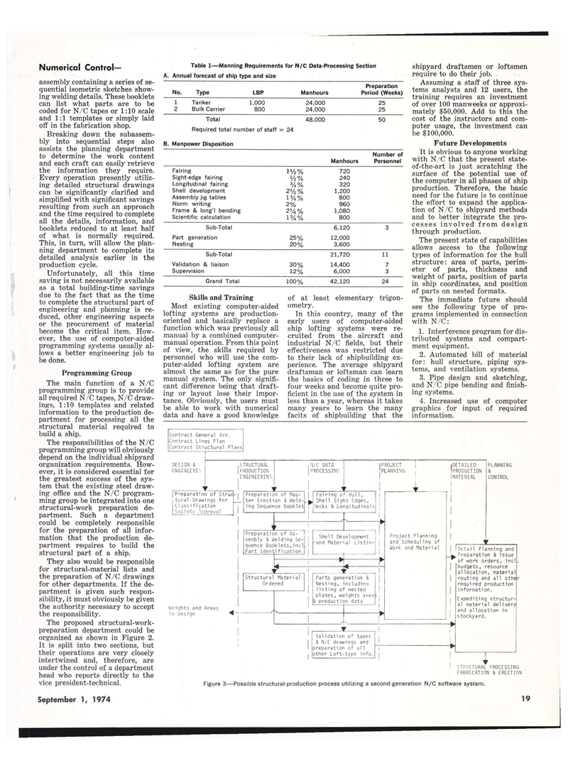
Figure 3—Possible structural-production process utilizing a second-generation N/C software system. 19
