Page 20: of Maritime Reporter Magazine (December 1978)
Read this page in Pdf, Flash or Html5 edition of December 1978 Maritime Reporter Magazine
 19
19
 21
21
The Third Generation Roll-On/Roll-Off Ship
The M/S Boogabilla
H. Ando, A. Miura and S. Namba* *Mr. Ando, deputy manager, No. 2 Ship Designing
Department, Nagasaki Shipyard & Engine Works;
Mr. Miura, project manager, Ship Engineering De- partment, and Mr. Namba, project manager, Ship
Engineering Department, Mitsubishi Heavy Indus- tries, Ltd., Japan, presented the paper abstracted here before a recent meeting of the New York
Metropolitan Section of The Society of Naval Ar- chitects and Marine Engineers. Copies of the paper may be obtained through the SNAME headquarters in New York.
The recently completed M/S Boogabilla is classed by its builders and owners as the third generation of deepsea roll-on/roll-off vessels. The ship incorporates several new items for this type of vessel, such as a large- bore, slow-speed diesel engine; three parallel trafficways, and a jumbo angled stern ramp.
The Boogabilla was designed and built by
Mitsubishi Heavy Industries, Ltd. at its
Koyagi Works of Nagasaki Shipyard for
Scan Carriers, under contract by Trans- atlantic Reederi. The owner's unique ro/ro service requirements also were integrated into the design.
The vessel has four cargo decks consisting of tank top (deck 1), weather deck (deck 4) and two in-between decks. A hoistable car- deck in the cargo space below deck 3 and two tiers of hoistable and partly fixed car- decks at the forward part of deck 3 are also provided. A large quarter stern ramp, de- signed for a total load of 400 tons, is fitted at the stern end of deck 3, from which car- goes are loaded or unloaded and distributed to other decks through onboard rampways.
The machinery space and accommodations are located aft. Deck 4, below the accommo- dations, also is utilized as a cargo space. A funnel for the engine exhaust is located on the starboard side aft and is also used as the stern-ramp post. In order to obtain ad- ditional versatility, breakbulk refrigerated cargo spaces and tallow-oil tanks are pro- vided in the aft part of deck 2 and the for- ward end of the cargo spaces respectively.
Cargo spaces, including the weather deck, are designed and equipped with a complete stowage pattern for containers. However, the capacity for carrying all kinds of gen- eral cargo was pronounced in the design cri- teria. All decks have neither sheer nor camber. Clear deck heights for cargo loading and other design conditions are: deck 1—10 feet 6 inches; deck 2—20 feet 8 inches; deck 3—20 feet 8 inches, and deck 4—17 feet 8M> inches (below deck 5) and elsewhere 20 feet 8 inches.
Fifty tons of axial load with six wheels, assuming fork lifts with a 20-foot container, a trailer loaded with two 20-foot containers,
LUF trailer loaded with eight 20-foot con- tainers and 150 tons payload wagon also were considered as design conditions. In ad- dition, the aft section of deck 3 is specially reinforced to load heavy cargo.
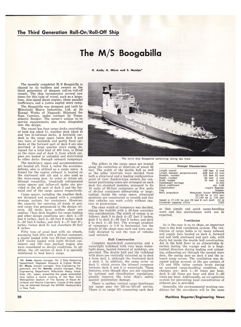
The ro/ro ship Boogabilla performing during sea trials.
The pillars in the cargo space are located along the centerline at intervals of about 52 feet. The width of the double hull as well as the pillar intervals were decided from both a structural and a loading configuration point of view. Sunken-type sockets for con- tainer positioning cones are arranged on each deck for. standard modules, arranged to fix 10 units of 20-foot containers or five units of 40-foot containers athwartship or longi- tudinal. Inside the cargo space, structural members are constructed so smooth and fair that vehicles can work safely without cau- tion to protrusions.
The clear width of rampways was decided, taking the forklift with a 20-foot container into consideration. The width of ramps is as follows: deck 3 to deck 4—27 feet 3 inches, deck 3 to deck 2—38 feet 5 inches, and deck 2 to deck 1—25 feet. The average gradient of rampways is 1:8 to horizontal, but the details of the shape near each end were care- fully designed to suit the type of vehicles used onboard.
Hull Construction
Complete double-hull construction and a watertight bulkhead with very large water- tight doors, located forward of midships, are provided. The double hull and the bulkhead with doors are vertically extended up to deck 4 from deck 1, although the freeboard deck is deck 3. In addition, the ramp cover on deck 3, which covers the inboard rampway between deck 3 and 2 is watertight. These features, even though they are not required by national and classification regulations, greatly improve the total ship's safety against penetration damage.
There is neither vertical cargo hatchways nor cargo gear for lift-on/lift-off service.
There is no cargo lift connecting each deck
Principal Characteristics
Length overall 749 feet 6 inch
Length between perpendiculars 688 feet 10 inch
Breadth, molded 105 feet 10 inch
Depth, molded 66 feet 3 inch
Draft, loaded 35 feet 5 inch
Deadweight tonnage 31,500
Block coefficient abt. 0.66
Classification Lloyd's Register
Flag Sweden
Main propulsion Mitsubishi Sulzer 9RND90M 30,150 hp @ 122 rpm 27,140 hp @ 118 rpm
Speed @ 27,140 hp and 29 feet 8 inch draft 22 kt
Container capacity (TEU) 1707 so that simple and quick cargo-handling work and less maintenance work can be expected.
Ventilation
As is the case in ro/ro ships, an important item is the hold ventilation system. The ven- tilation of cargo holds is by many exhaust and supply fans located on deck 4, forward end and both starboard and port side, with ducts led inside the double hull construction.
Air in the hold flows in an athwartship di- rection during the voyage and in a longi- tudinal direction during loading and unload- ing, exhausting air through the opened stern door, the casing door on deck 4 and the in- board ramp covers. The ventilation was de- signed taking account of the gas content of
CO and NOx below certain levels during an assumed cargo-handling condition. Air changes are: deck 1—30 times per hour, deck 2—25 times per hour and deck 3—20 times per hour. Additionally, an air-agitation system for preventing local concentration of exhaust gas is provided.
Generally, the environmental working con- ditions for the stevedores will be the same 10 Maritime Reporter/Engineering News
