Page 21: of Maritime Reporter Magazine (December 1978)
Read this page in Pdf, Flash or Html5 edition of December 1978 Maritime Reporter Magazine
 20
20
 22
22
on all decks although there are a different number of air changes per hour. It is not sufficient to use the number of air changes as a design criteria, and consequently new criteria was developed and used for this vessel.
As to fire protection for cargo holds a smoke-detecting system, gas-detecting sys- tem and carbon-dioxide fire-extinguishing system are provided. The carbon dioxide sys- tem is of the low-pressure type and has a quantity corresponding to 45 percent of the largest compartment. Two-thirds of the gas capacity can be discharged within 10 min- utes so as to meet IMCO's latest recom- mendations.
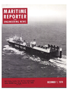
Section through the engine room showing location of ramps.
Hydrodynamic Design
To fulfill the basic characteristics of the vessel, such as, geometrical configurations, deadweight, ship's speed, trim and stability and precautions for vibrations, ship's hull form was carefully developed on the basis of extensive builder's experience and investi- gations in this field.
As the ship's breadth and draft were given by the owner from the cargo handling and operation point of view, the ship's length was the only variable parameter in the opti- mization of the ship's dimension. After para- metric studies of variation in ship's length, block coefficient and required power of the main engine, a ship's length of 688 feet 10 inches was selected.
So as to obtain an optimum hull form, five kinds of hull forms were tested. Start- ing with the original hull form designed on the basis of existing data, investigations were made into the effect of size and shape of bulbous bow, load waterline and frame line shapes.
The aft body lines were very carefully designed to minimize the propeller exciting forces with an improved wake distribution and frame lines as well as for obtaining a good performance of ship's speed. The dif- ficulty of the design of the aft body con- sisted of resolving inconsistent demands.
Full breadth was required even at the aft end, and the draft was shallow compared with the breadth and the higher main en- gine power (larger propeller diameter).
Safety Measures
Various safety measures have been adopt- ed at the owner's request.
The rampway between deck 3 and deck 2 is covered by a watertight ramp cover, di- viding the vessel into two compartments horizontally. The cover is designed to have watertightness with flooding above or below deck 3. Bilge suction lines from deck 3 are directly led to the engine room. These lines are separated from those from deck 1.
Eight sets of freeing ports with valves with a l^/a-inch diameter are arranged on the side shell just above deck 3. The valves can be remotely controlled from the deck control room with hydraulic devices. These freeing ports are provided for releasing the water directly overboard.
A watertight bulkhead with very large watertight doors is arranged between the decks from deck 1 to deck 4, on a vertical line, in order to divide the cargo space into two compartments veritcally. These doors were carefully designed and arranged not to interfere with the requirements for easy cargo handling.
Pipe passages on both sides on deck 1 are cross-connected at the forward end, which enables the list of the vessel to be smaller automatically when one side passage is damaged.
Double-hull construction was provided from deck 1 up to the weather deck, al- though deck 3 is designated as the freeboard deck. This construction makes the inner sur- face flat which enables rapid cargo handling and also makes the ship safer. The double hull between deck 3 and deck 4 contributes to the adjustment of the rolling period in ballast conditions by providing ballast-water tanks as well as increasing the residual buoy- ancy and residual BM when full vertical pen- etration should occur.
Each ventilating duct from the cargo spaces was fitted with a watertight damper on the top of the fan, which is remotely con- trolled from the deck control room. It pre- vents the air from flowing out freely and makes the flooding time longer when the cargo space is flooded, as well as acting as a fire damper.
All ventilating ducts for cargo spaces are independently led from the weather deck to each deck concerned and the ducts are led with triple hull construction below the free- board deck to avoid direct flooding into the cargo spaces from a small damage to the outer shell.
Escape trunks are arranged from the cargo spaces to the weather deck through the double-hull construction and a watertight door is provided on every entrance to the trunk to avoid free connection between each deck space and also to avoid direct flooding into the cargo spaces by damage to the outer shell.
No side port opens directly into the en- gine room or cargo space below the freeboard deck. This concept avoids eventual flooding from the side port when it is opened or damaged.
Design Items
One of the main points of the vessel is the installation of a slow speed diesel engine (Mitsubishi Sulzer 9RND90M rated at 30,150 hp maximum and 27,140 hp normal rating, 122 rpm and 118 rpm respectively) for pro- pulsion. Generally, the slow-speed diesel en- gine is advantageous due to the lessened fuel costs of heavy fuel oil, lower lubricating-oil consumption, and less maintenance due to the smaller number of cylinders. However, the engine height required for overhauling is a major disadvantage for ro/ro arrange- ments.
This problem was studied together with the machinery room arrangement and the inboard traffic arrangement. The machinery is arranged within the limited space incor- porating the main engine, four diesel alter- nators, engine control room, work shops and
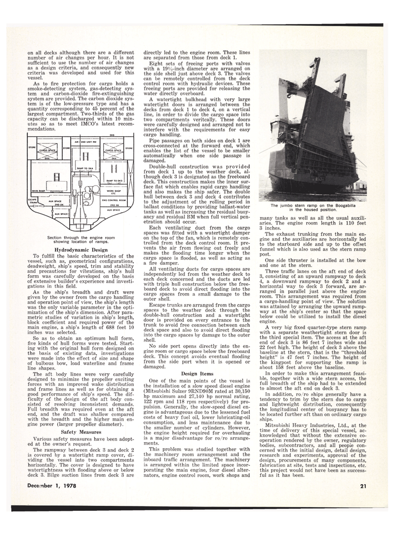
The jumbo stern ramp on the Boogabilla in the housed position. many tanks as well as all the usual auxili- aries. The engine room length is 110 feet 3 inches.
The exhaust trunking from the main en- gine and the auxiliaries are horizontally led to the starboard side and up to the offset funnel which is also used as the stern ramp post.
One side thruster is installed at the bow and one at the stern.
Three traffic lanes on the aft end of deck 3, consisting of an upward rampway to deck 4, a downward rampway to deck 2 and a horizontal way to deck 3 forward, are ar- ranged in parallel just above the engine room. This arrangement was required from a cargo-handling point of view. The solution was attained by arranging the upward ramp- way at the ship's center so that the space below could be utilized to install the diesel engine.
A very big fixed quarter-type stern ramp with a separate weathertight stern door is the third special item. The access at the aft end of deck 3 is 86 feet 7 inches wide and 22 feet high. The height of deck 3 above the baseline at the stern, that is the "threshold height" is 47 feet 7 inches. The height of the kingpost for supporting the ramp is about 158 feet above the baseline.
In order to make this arrangement feasi- ble, together with a wide stern access, the full breadth of the ship had to be extended to almost the aft end on deck 3.
In addition, ro/ro ships generally have a tendency to trim by the stern due to cargo and lightweight distribution, consequently the longitudinal center of buoyancy has to be located further aft than on ordinary cargo ships.
Mitsubishi Heavy Industries, Ltd., at the time of delivery of this special vessel, ac- knowledged that without the extensive co- operation rendered by the owner, regulatory bodies, subcontractors, and all peopie con- cerned with the initial design, detail design, research and experiments, approval of the design, procurements of many components, fabrication at site, tests and inspections, etc. this project would not have been as success- ful as it has been.
December 1, 1978 13
