
Page 39: of Maritime Reporter Magazine (October 2012)
Marine Design & Construction
Read this page in Pdf, Flash or Html5 edition of October 2012 Maritime Reporter Magazine
 38
38
 40
40
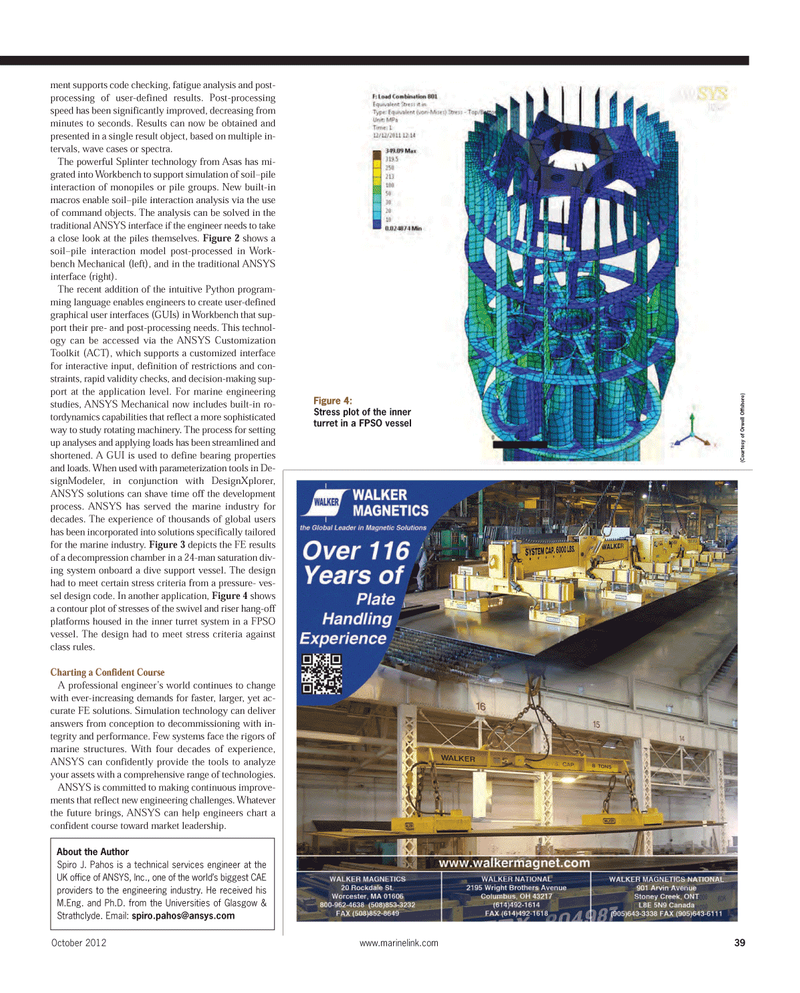
ment supports code checking, fatigue analysis and post- processing of user-defined results. Post-processing speed has been significantly improved, decreasing from minutes to seconds. Results can now be obtained and presented in a single result object, based on multiple in-tervals, wave cases or spectra. The powerful Splinter technology from Asas has mi- grated into Workbench to support simulation of soil?pile interaction of monopiles or pile groups. New built-in macros enable soil?pile interaction analysis via the useof command objects. The analysis can be solved in the traditional ANSYS interface if the engineer needs to take a close look at the piles themselves. Figure 2 shows a soil?pile interaction model post-processed in Work- bench Mechanical (left), and in the traditional ANSYS interface (right). The recent addition of the intuitive Python program- ming language enables engineers to create user-defined graphical user interfaces (GUIs) in Workbench that sup- port their pre- and post-processing needs. This technol- ogy can be accessed via the ANSYS Customization Toolkit (ACT), which supports a customized interface for interactive input, definition of restrictions and con- straints, rapid validity checks, and decision-making sup- port at the application level. For marine engineering studies, ANSYS Mechanical now includes built-in ro- tordynamics capabilities that reflect a more sophisticatedway to study rotating machinery. The process for setting up analyses and applying loads has been streamlined andshortened. A GUI is used to define bearing properties and loads. When used with parameterization tools in De- signModeler, in conjunction with DesignXplorer, ANSYS solutions can shave time off the development process. ANSYS has served the marine industry for decades. The experience of thousands of global users has been incorporated into solutions specifically tailored for the marine industry. Figure 3 depicts the FE resultsof a decompression chamber in a 24-man saturation div- ing system onboard a dive support vessel. The design had to meet certain stress criteria from a pressure- ves- sel design code. In another application, Figure 4 shows a contour plot of stresses of the swivel and riser hang-off platforms housed in the inner turret system in a FPSOvessel. The design had to meet stress criteria against class rules.Charting a Confident Course A professional engineer?s world continues to change with ever-increasing demands for faster, larger, yet ac- curate FE solutions. Simulation technology can deliver answers from conception to decommissioning with in-tegrity and performance. Few systems face the rigors of marine structures. With four decades of experience, ANSYS can confidently provide the tools to analyze your assets with a comprehensive range of technologies. ANSYS is committed to making continuous improve- ments that reflect new engineering challenges. Whatever the future brings, ANSYS can help engineers chart a confident course toward market leadership. October 2012www.marinelink.com 39About the AuthorSpiro J. Pahos is a technical services engineer at the UK office of ANSYS, Inc., one of the world?s biggest CAE providers to the engineering industry. He received his M.Eng. and Ph.D. from the Universities of Glasgow & Strathclyde. Email: [email protected] Figure 4: Stress plot of the inner turret in a FPSO vessel (Courtesy of Orwell Offshore) MR#10 (34-41):MR Template 10/4/2012 11:01 AM Page 39
