
Page 42: of Maritime Reporter Magazine (October 2012)
Marine Design & Construction
Read this page in Pdf, Flash or Html5 edition of October 2012 Maritime Reporter Magazine
 41
41
 43
43
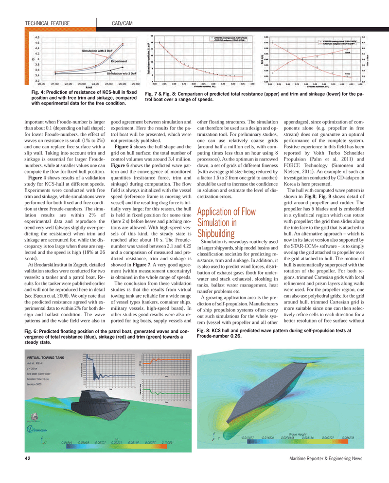
42Maritime Reporter & Engineering News important when Froude-number is larger than about 0.1 (depending on hull shape);for lower Froude-numbers, the effect of waves on resistance is small (1% to 2%) and one can replace free surface with a slip wall. Taking into account trim and sinkage is essential for larger Froude- numbers, while at smaller values one can compute the flow for fixed hull position. Figure 4 showsresults of a validation study for KCS-hull at different speeds. Experiments were conducted with freetrim and sinkage, while simulations wereperformed for both fixed and free condi- tion at three Froude-numbers. The simu- lation results are within 2% ofexperimental data and reproduce the trend very well (always slightly over-pre- dicting the resistance) when trim andsinkage are accounted for, while the dis- crepancy is too large when these are neg- lected and the speed is high (18% at 26knots).At BrodarskiInstitut in Zagreb, detailedvalidation studies were conducted for two vessels: a tanker and a patrol boat. Re- sults for the tanker were published earlier and will not be reproduced here in detail(see Bucan et al, 2008). We only note that the predicted resistance agreed with ex- perimental data to within 2% for both de-sign and ballast condition. The wave patterns and the wake field were also in good agreement between simulation andexperiment. Here the results for the pa- trol boat will be presented, which werenot previously published. Figure 5 shows the hull shape and the grid on hull surface; the total number of control volumes was around 3.4 million. Figure 6 shows the predicted wave pat- tern and the convergence of monitored quantities (resistance force, trim andsinkage) during computation. The flow field is always initialized with the vessel speed (reference frame is moving with vessel) and the resulting drag force is ini- tially very large; for this reason, the hull is held in fixed position for some time (here 2 s) before heave and pitching mo- tions are allowed. With high-speed ves- sels of this kind, the steady state isreached after about 10 s. The Froude- number was varied between 2.1 and 4.25 and a comparison of measured and pre-dicted resistance, trim and sinkage isshowed in Figure 7 . A very good agree- ment (within measurement uncertainty)is obtained in the whole range of speeds.The conclusion from these validation studies is that the results from virtualtowing tank are reliable for a wide range of vessel types (tankers, container ships, military vessels, high-speed boats). In other studies good results were also re-ported for tug boats, supply vessels and other floating structures. The simulation can therefore be used as a design and op-timization tool. For preliminary studies, one can use relatively coarse grids (around half a million cells, with com-puting times less than an hour using 8processors). As the optimum is narrowed down, a set of grids of different fineness (with average grid size being reduced by a factor 1.5 to 2 from one grid to another) should be used to increase the confidence in solution and estimate the level of dis- cretization errors. Application of Flow Simulation in ShipbuildingSimulation is nowadays routinely used in larger shipyards, ship model basins and classification societies for predicting re- sistance, trim and sinkage. In addition, itis also used to predict wind forces, distri-bution of exhaust gases (both for under- water and stack exhausts), sloshing in tanks, ballast water management, heat transfer problems etc. A growing application area is the pre- diction of self-propulsion. Manufacturers of ship propulsion systems often carryout such simulations for the whole sys-tem (vessel with propeller and all other appendages), since optimization of com-ponents alone (e.g. propeller in freestream) does not guarantee an optimalperformance of the complete system.Positive experience in this field has been reported by Voith Turbo Schneider Propulsion (Palm et al, 2011) and FORCE Technology (Simonsen and Nielsen, 2011). An example of such an investigation conducted by CD-adapco in Korea is here presented. The hull with computed wave pattern is shown in Fig.8; Fig. 9 shows detail of grid around propeller and rudder. The propeller has 5 blades and is embeddedin a cylindrical region which can rotate with propeller; the grid then slides alongthe interface to the grid that is attached to hull. An alternative approach ? which is now in its latest version also supported by the STAR-CCM+ software ? is to simply overlap the grid attached to propeller over the grid attached to hull. The motion of hull is automatically superposed with therotation of the propeller. For both re- gions, trimmed Cartesian grids with localrefinement and prism layers along walls were used. For the propeller region, one can also use polyhedral grids; for the gridaround hull, trimmed Cartesian grid ismore suitable since one can then selec-tively refine cells in each direction for a better resolution of free surface without Fig. 6: Predicted floating position of the patrol boat, generated waves and con- vergence of total resistance (blue), sinkage (red) and trim (green) towards a steady state.TECHNICAL FEATURE CAD/CAM Fig. 4: Prediction of resistance of KCS-hull in fixed position and with free trim and sinkage, compared with experimental data for the free condition. Fig. 7 & Fig. 8: Comparison of predicted total resistance (upper) and trim and sinkage (lower) for the pa- trol boat over a range of speeds. Fig. 8: KCS hull and predicted wave pattern during self-propulsion tests at Froude-number 0.26. MR#10 (42-49):MR Template 10/4/2012 11:14 AM Page 42
