
Turbocharger Modification
Cost Effective Solution for Fuel Saving and Emission Control
A turbocharger’s efficiency significantly influences diesel engine performance. For example, a turbocharger (TC) efficiency increase of one percent results in the following improvements, under constant engine power:
• Supercharged air pressure increases 1% - 2%
• Fuel consumption decreased
0.4% - 0.6%
• NOx emission decreased 5% - 8%
• Exhaust gas temp. down 2% - 4%
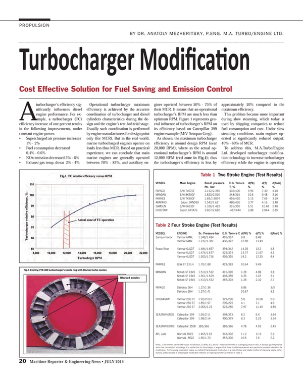
Operational turbocharger maximum efficiency is achieved by the accurate coordination of turbocharger and diesel cylinders characteristics during the design and the engine’s test-bed trial stage. Usually such coordination is performed by engine manufacturers for design point only (for MCR). But in the real world, marine turbocharged engines operate on loads less than MCR. Based on practical experience, we can conclude that main marine engines are generally operated between 70% - 85%, and auxiliary engines operated between 50% - 75% of their MCR. It means that an operational turbocharger’s RPM are much less than optimum RPM. Figure 1 represents general influence of turbocharger’s RPM on its efficiency based on Caterpillar 399 engine example (M/V Seaspan Greg).
As shown, the maximum turbocharger efficiency is around design RPM (near 20,000 RPM), where as the actual operational turbocharger’s RPM is around 12,000 RPM (red zone in Fig.1); thus the turbocharger’s efficiency is less by approximately 20% compared to the maximum efficiency.
This problem became more important during slow steaming, which today is used by shipping companies to reduce fuel consumption and cost. Under slow steaming conditions, main engines operated at significantly reduced output: 40% - 60% of MCR.
To address this, M.A.Turbo/Engine Ltd. developed turbocharger modification technology to increase turbocharger efficiency while the engine is operating at reduced load. The modification comprises computer program analysis, the method of reducing the area of the turbine’s nozzles; and “waste gate” (WG) arrangement.
The computer program establishes the optimum nozzle ring area FOPT for the given engine output and type of turbocharger. The difference between the existing nozzle ring area F and FOPT gives the new nozzle ring area required to achieve the improvement in engine performance at a reduced load. The computer program determines a new boost air pressure, corresponding to the reduced nozzle ring area, and this new increased air pressure is compared with the design boost air pressure at the engine’s MCR.
To avoid possible surging, the new increased air pressure cannot be higher than the design air boost pressure at MCR. As a rule, the reduced nozzle ring area is in such proportion that increased scavenging air pressure at operating load is 10% - 15% less than the design scavenging air pressure at engine’s MCR. That means that any engine with a modified turbo nozzle ring can be loaded, if necessary, at up to 85% of MCR without sacrificing turbocharger reliability.
A turbo nozzle’s area reduction is achieved by blocking a few nozzles on existing nozzle rings: nozzles, which should be blocked, are covered by flat stainless plate (Figure 2). The plate is secured by stainless screws. If required reduction of nozzle ring area is less than 10%, simple bending of nozzle blades can do it. There is no need to buy a new nozzle ring.
The described method of reducing the existing nozzle ring area does not generate any additional stresses to the nozzle or rotating blades.
On the contrary, the thermal stresses become less, due to reduced exhaust gas temperature. Both bending and tensile stresses in the blades are less than at design engine load because the turbocharger RPM remains lower than admissible RPM at MCR. It means that there is no potential danger to the normal turbocharger operation.
M.A.Turbo/Engine Ltd. (in cooperation with Vicmar Ltd.) has implemented the turbo nozzle ring modification on 64 different engines worldwide. Some results attributed to the nozzle ring modifications are shown in Table 1 and Table 2. As can be seen, the fuel savings ranged from 2.8% to 5.0%. Simultaneously, exhaust gas temperature and NOx emission was reduced. The actual boost air pressure is much less than at MCR point: 62% compared to MCR and only 58% of what turbocharger is capable to provide. Accordingly, the turbocharger can supply much more air than it supplies at reduced load, thus reducing exhaust gas temperature and specific fuel consumption.
However, it is obvious that sometimes the main or the auxiliary engine needs to be operated at MCR. For these cases M.A. Turbo/Engine developed the WG arrangement shown in Figure 3. As shown, an electronically operated WG valve is installed before turbine inlet. This valve receives signal from either turbocharger’s RPM or scavenging pressure and maintain turbo RPM around optimum efficiency during any load.
Benefits of Turbocharger Modification include: Reduced operational expenses due to less fuel consumption of up to 5%; Less maintenance cost; Greenhouse gas emissions reduction; TC modification cost is 3 – 5 times less than turbocharger replacement; Pay-back period is usually 1 – 1.5 year.
(As published in the July 2014 edition of Maritime Reporter & Engineering News - http://magazines.marinelink.com/Magazines/MaritimeReporter)
Read Turbocharger Modification in Pdf, Flash or Html5 edition of July 2014 Maritime Reporter
Other stories from July 2014 issue
Content
- Editorial: Gas ... It's Both the Question & the Answer page: 6
- FORAN Users Meeting (FORUM 2014) page: 11
- Harnessing the Wind for Auxiliary Propulsion page: 12
- OSRO: The Child of Necessity page: 14
- Electronic Navigation & Dispute Resolution: Coming of Age page: 16
- The Cause behind the Clause Piers & Docks Insurance page: 18
- AIS Data for Emissions Reduction page: 19
- Turbocharger Modification page: 20
- Interview: Roberto Cazzulo Talks Class Trends page: 22
- Desulfurization of Exhaust Gases in Shipping page: 26
- FLNG Prelude: A New Dawn in the Age of Maritime & Energy page: 30
- Prelude By the Numbers page: 36
- Floating Production: $1.2b Speculative FLNG Ordered page: 38
- Private Equity Drives New Ship Buys page: 40
- Business is Brisk at Posidonia in Athens page: 44
- American P&I Club Rings in Posidonia page: 47
- Unified Emissions Monitoring: Turbulo Bluemon page: 50
- TOTE Ship Receives Powerplant page: 50
- Thrustmaster, DOEN Ink Deal page: 50
- gplink: Remote Monitoring from Finning page: 51
- New Emergency Genset from Cummins page: 51
- Repowered Tug Tows Nonstop page: 51
- FPP Design from Wärtsilä page: 51
- Dynaligner Aims to Eliminate Shaft Misalignment page: 52
- Metal Thickness Gauge Launched page: 52
- New A/C Chiller for Medium to Large Yachts page: 52
- Bernard Offers MIG Gun Customization page: 52
- MEGAFIL Welding Wires page: 53
- Air Hoists Offer Safe & Efficient Lifting page: 53
- CS Unitec Floor Planer Helps Prep for Recoating page: 54
- New Products for Engineroom Ventilation page: 54
- Aluminum MIG Push-Pull Welding Packages page: 54
- Aluminum Oxide Fiber Discs page: 54
- New Cleaning Water Jet Nozzle page: 54
- Dr. Shrink's Extra-Wide Shrink Wrap page: 54
- ABS CErtifies SCIGRIP Adhesives page: 54
- ENC Production Software Launched page: 55
- New Spoolmatic Pro from Miller page: 55
- Bernard’s ‘Best of the Best’ Platform page: 55
- Combat Cold Corrossion via Condition Monitoring page: 56
- Mississippi Hosts Fourth Annual National SeaPerch Challenge page: 57
