
Conflicting Objectives in Ship Design
Enviro, Safety Regulations Conspire to Complicate the Marine Classification Business
“ABS is first and foremost a safety company,” says Richard Korpus, “but safety can arise on many different fronts. It can refer to the safety of a high-valued asset, for the people who work on that asset, for the environment where the asset operates, or even for the financial security of the owners and operators of that asset.”
Dr. Korpus is Chief Scientist, Computational Fluid Dynamics (CFD) for the American Bureau of Shipping. In this role Korpus supports the Chief Technology Officer (CTO) and underlying organizations through a focus on developing and applying CFD technology. He believes CFD has the potential to change how some of the most challenging problems in marine and offshore classification are solved in the future.
“This organization has a reputation as an industry leader, and we’re using CFD to extend that reputation by offering state-of-the-art services new to the classification business,” said Korpus. In this article, the reader is introduced as to how CFD is changing ABS’ marine technology business by providing designers, owners and operators a means to improve vessel fuel efficiency, lower environmental impact, and maintain the highest level of safety.
CFD Supports a Proactive Business Model
Shipping is the lifeblood of the world economy carrying 90 percent of international trades worldwide. A variety of organizations, including the International Marine Organization (IMO), national Coast Guards, and regional Port Authorities, impose regulations to ensure the safety of cargos, people, and the environment. These regulations change regularly, and a Classification Society needs to react quickly. When combined with ship owners’ continued motivation to minimize operating cost, it is becoming essential that every sector of the marine industry find efficient design strategies to satisfy environmentally-friendly and safety regulations. The net effect is an enhanced competitiveness where innovative solutions are essential to survival. Examples of new challenges include: optimizing hull resistance and propulsive power; deployment of biodegradable oils to lower the risk of water contamination; development of Energy Saving Devices (ESDs); and methods to “scrub” engine emissions. Each of these innovations comes with its own business and technical challenges, and ABS has chosen to respond proactively by investigating solutions before their clients encounter difficulties. CFD is an essential part of that process.
One timely example is the increasingly demanding environmental regulation known as the Energy Efficiency Design Index (EEDI). The index is a means to enforce reductions in greenhouse gas emissions, but in conjunction with owners’ desires to minimize fuel consumption may push designers to install less powerful propulsion engines. Since total installed power is an important variable for the safety of ships in bad weather, the requirements for low emissions and safe power margin could come into conflict. ABS is taking a proactive role in helping to avoid such conflicts by using CFD to quantify minimum safe levels of power.
Being proactive (as opposed to reactive) requires an engineering approach built on pre-established CFD “best practices” to minimize response time. Best practices typically focus on a single class of CFD application, but at ABS these are motivated by the more practical business objectives of class customers. Practices exist to guide development of ships and platforms to be more environmental, safer, fuel efficient, and cost-effective. Typical CFD-related service offerings include:
▪ Guide hull and propeller design to minimize operating cost
▪ Ensure safe power margins are maintained as installed power is decreased
▪ Ensure adequate maneuvering and dynamic stability margins are maintained
▪ Assist propeller shaft and stern tube design to avoid bearing damage
▪ Assist selection and improvement of Energy Saving Devices (ESDs)
▪ Provide structural load estimates due to sloshing liquid cargoes
▪ Provide structural load estimates imposed by extreme wind and wave events
▪ Guide cargo distribution to minimize motion, structural loading, or slamming in a seaway
▪ Advise operators about the most fuel efficient cargo distribution and operating trims
▪ Develop procedures to minimize boil-off of Liquefied Natural Gas (LNG) cargos
▪ Guide redesign to accommodate the trend towards slow steaming.
Best practices help ABS customers and prospective clients look ahead before committing to a particular design. They allow assessment of a design’s performance, or its compliance with environmental and safety regulations (such as EEDI), at an early stage of a project. An additional advantage is that Best Practices homogenize the quality of ABS’ CFD products and services. Even though they have been using CFD (including STAR-CCM+®) for many years, Best Practices ensure that ABS engineers from different offices, different levels of CFD experience, or with different customer requirements all deliver the expected level of accuracy in a predictable period of time. Consistent quality of results is guaranteed without spending extra man-hours repeating grid refinement, time step, or turbulence modeling studies.
An example is provided in the next section where best practices for propeller optimization are demonstrated.
Design Optimization
In order to improve a ship’s operating efficiency it is necessary to simultaneously address its hull resistance, propulsive efficiency, and engine performance. Each affects the other, and the process is even more challenging when multiple optimization objectives are contradictory in nature. For instance, reducing the main engine size can improve overall efficiency in terms of lower fuel consumption and greenhouse gas emissions, but conflicts with safety-oriented requirements for reserve power. Without adequate reserve power a vessel might have maneuvering problems as wind and wave loads increase in bad weather. In such a case optimization requires a subtle balance between economy and safety -- or at the very least inequality constraints to ensure minimal acceptable values for each objective.
Propeller Design by Full Scale Simulation
Propeller design is one of the most important factors affecting operating efficiency, and yet it has been performed more or less the same way for decades. The problem is indeed difficult because the propeller operates in a hull viscous wake that varies both spatially and temporally. Traditionally a model test is performed without the propeller present. The wake is measured and then extrapolated to full-scale. The result is averaged circumferentially at each radius to provide a steady inflow, and the propeller designed for that condition. But with modern CFD and optimization, it is no longer necessary to tolerate the inaccuracies of extrapolation or steady inflow assumptions. The propeller can be designed or optimized at full scale, in situ behind the ship, even when the wake is unsteady and varies in three dimensions. A design developed using full-scale, unsteady CFD will be more efficient due to accurately accounting for propeller/hull interaction, and can be made to produce less unsteady force (vibration), off-axes loading, and cavitation.
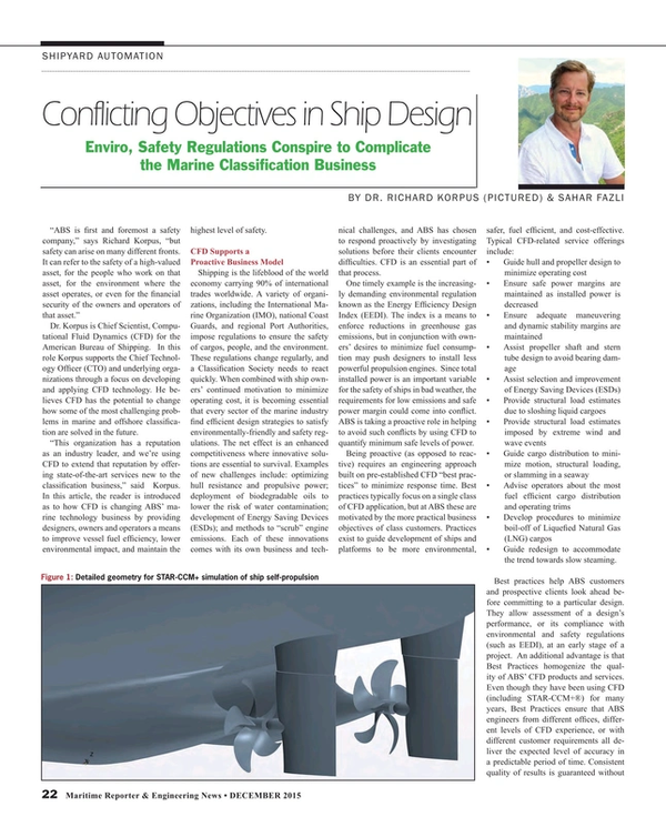
Figure 1 shows a typical self-propelled ship simulation and Figure 2 the types of propeller inflow (hull wake) that results from different modelling assumptions. Figure 2 demonstrates the severity of inaccuracies that are expected when using un-propelled or model-scale test data to predict actual propeller inflow. Note that the model scale wake looks nothing like the full-scale equivalent. Similarly, the normal wake (without propeller) looks nothing like the effective wake (with propeller). A model test provides data like that shown in the upper left figure, but the operating condition for which a propeller should be designed is like that in the lower right.
To demonstrate the advantages of design by CFD, engineers at ABS leveraged STAR-CCM+‘s sliding mesh and overset grid techniques to simulate full-scale propellers rotating in the actual full-scale unsteady hull wake. CD-adapco’s HEEDS optimization package was employed to search through design space, and a variety of parameterizations tested including radial distributions of pitch, chord, rake, and skew. HEED’s SHERPA algorithm is employed to find the design with minimal shaft power at a prescribed thrust. The individual software elements are shown in the schematic of Figure 3.
For a real-world design, the story is more complicated because of the phenomenon of cavitation. If pressure falls below the thermodynamic boiling point, water evaporates to vapor. With low enough pressure (such as might be found on a propeller blade at high lift coefficients) this can happen at any temperature. When pressure again increases the process reverses and vapor condenses, sometimes violently. The more violent condensations can actually erode away a solid metal blade. It is also notable that not all “good” designs are created equal. Two blades with equal total lift and drag might exhibit different levels of cavitation depending on the local distributions of pressure. Figure 4 shows an example of cavitation and cavitation damage. ABS design optimizations avoid this problem by checking minimum blade surface pressure for every design and passing the results back to HEEDS for providing an inequality constraint. Excessive cavitation is avoided by not allowing minimum blade pressure to get any less than that of an acceptable baseline design.
Single Objective Approach
The method is demonstrated for a twin-screw LNG carrier at a single speed and cargo load. The hull is left unchanged, and propeller parameterized for varying radial distributions of pitch and chord. Once the base design is solved, HEEDS’ SHERPA algorithm uses a combination of population-based and gradient-based optimization methods to explore the whole design space. Each design is tested at multiple shaft speeds, and the objective function (shaft horsepower) is chosen for the speed which delivers the prescribed thrust. Minimum blade surface pressure is found over one complete revolution at the thrust balance point, and the result returned to HEEDS to provide the cavitation inequality constraint.
The level of improvement possible is dependent on how a design is parameterized and on how many design evaluations are permitted. In the present example the radial distributions of pitch and chord are defined by just five parameters and SHERPA is allowed just 150 design evaluations. The baseline propeller was taken from a high-end designer who had already optimized the unit using existing analysis technology. Results are summarized in the HEEDS output shown in Figure 5.
Even for this relatively restrictive example, ABS engineers found power reductions around 2 percent, which for larger ships corresponds to as much as $500,000 per year savings. But as Dr. Korpus points out, “The point is even more fundamental than the huge cost savings. For more than 100 years ship designers have built ships using the evolutionary approach – one small improvement per design generation. Within the last few years CFD has provided a ground breaking technology to enable the revolutionary approach – true optimization for every design generation.”
Multi-Objective Optimization
The single-objective approach provides an effective philosophy to identify substantial fuel savings, but does not account for the above mentioned issue of reserve engine capacity for maneuvering in extreme weather. Ship engines spend most of their life operating at a power less than their Maximum Continuous Rating (MCR). But if the propeller and engine are optimized simultaneously, a power plant will be selected with just enough power to satisfy the design condition. Normal operations will require 100 percent MCR and nothing is left for bad weather. Conventional design wisdom applies a 15 percent “sea margin” to cover such contingencies, and one might be tempted to just add that margin after the optimization is complete. But in reality the required margin is a function of the other design variables, so a multi-objective approach is required. Ideally, a designer should be provided with a range of designs (the so-called Pareto frontier) that prioritize the objectives of fuel saving and safe maneuvering independently.
Unfortunately, simulations of self-propelled ship maneuvering are still very time-consuming. Even a single maneuver at a single speed in a single wind and sea condition requires many days of computer run time. It is impractical (at this point in time) to incorporate heavy weather maneuvering into a multi-objective optimization. In lieu of this, it is crucial to have a precise understanding of the minimum power margin required in adverse conditions, and also for how that minimum is affected by the other optimized variables. To provide this knowledge the CFD group at ABS conducts maneuvering simulations in various sea conditions and power settings. Typical rudder motions are applied and STAR-CCM+’s DFBI capability is used to predict the ship’s trajectory. A given level of power is considered safe if the vessel can turn and accelerate under the prescribed rudder motion. The goal is to build a database of acceptable sea margins that can be applied until the multi-objective approach becomes more viable.
A Practical Alternative to Multi-Objective
Developing this database requires a huge number of simulations. A variety of different ship types and sizes need to be tested over a range of weather conditions. In each case a range of power settings have to be applied to identify the point at which a vessel can no longer maneuver in the prescribed weather condition. The approach is demonstrated using a generic Very Large Crude Carrier (VLCC) trying to turn in 5.5 meter beam seas and 37 knots of side wind. Figure 6 shows the overset grid in a large background earth-fixed domain with a total of 7M trimmed hexahedral cells. The simulation starts with the ship at low speed and straight rudder to build fully-developed Kelvin and viscous wakes. The vessel is free to move in six degrees-of-freedom so the effects of added resistance and lost propulsive efficiency are included. Once the wakes are developed (and propeller forces stabilized), the rudder is put over 20 degrees and the power increased to full.
Simulations are conducted at different power levels under both full load and ballast draft conditions. If the prescribed maximum power is acceptable, the vessel accelerates under the influence of its own propulsive and rudder forces. At power levels below some point the ship can no longer overcome forces and moments imposed by the wind and waves, and just blows sideways. Figure 7 shows an example where the power is sufficient for a complete turn, whereas Figure 8 shows the trajectory from a vessel with lower maximum power. Note that in Figure 8 the vessel is seen to drift three-quarters of a boat length to leeward before starting to recover distance back to windward. The small high speed oscillations superimposed on top of the curves are due to vessel motions over individual waves. It is interesting that even though the turn rate (yaw angle versus time) becomes steady about half way through the simulation, the vessel is only just managing to halt its slide to leeward near the end of the simulation. The maximum power used for this second example might be considered close to the minimum safe amount.
Summary
CFD has become a practical tool in almost every sense. This is true not just from the technical point of view, but from the business point of view as well. It enables a proactive approach to solving client problems, and provides the means to revolutionize a maritime industry that is traditionally evolutionary in nature. Design optimization is finally becoming a reality, and even though some problems may still be time-consuming (e.g. maneuvering in a seaway), CFD can be expected to play an increasingly prominent role in the marine and offshore business sectors.
The Author
Dr. Richard Korpus is Chief Scientist for the American Bureau of Shipping (ABS), where he is responsible for integration and quality control of CFD services worldwide. Since joining ABS in 2013, Dr. Korpus has matured CFD into an essential part of ABS’ technology offerings, and developed new client services to ensure ABS remains ahead of the competition. CFD is now used over a wide range of marine and offshore applications to support customer requests to increase operating efficiency, enhance environmental performance, and improve safety.
(As published in the December 2015 edition of Maritime Reporter & Engineering News - http://magazines.marinelink.com/Magazines/MaritimeReporter)
Read Conflicting Objectives in Ship Design in Pdf, Flash or Html5 edition of December 2015 Maritime Reporter
Other stories from December 2015 issue
Content
- Arctic Coast Guard Forum: Eyes and Ears Up North page: 10
- New Roles for Satcoms in Autonomous Shipping page: 12
- It’s Time to End the MARPOL Merry-go-round page: 16
- Tankers, Bulkers & the Increased Need for Software Solutions page: 18
- Conflicting Objectives in Ship Design page: 22
- Gray Water & Bilge Water: Taking Steps to Clean Up the Ocean Environment page: 28
