
Page 45: of Offshore Engineer Magazine (Dec/Jan 2014)
Read this page in Pdf, Flash or Html5 edition of Dec/Jan 2014 Offshore Engineer Magazine
 44
44
 46
46
12 most challenging pipeline projects
Pipelines
Pipeline Project/ Max Water Length Associated Install Associated
Field Project depth (ft) (mi)CommodityAssociated FieldStatus Country Year Field Operator
Great White, Silvertip
Perdido (GoM) 9701 8Oil ProducingUnited States2009Shell and Tobago
Under
Stones (GoM) 9586 13 Oil Stones- FPSO United States 2013 Shell
Development
Chinook (GoM) 887711GasCascade -Chinook ProducingUnited States2009Petrobras
Under
Lucius (GoM) 8755 144 Oil Lucius United States2011Apache
Development
Under
Lucius (GoM) 8755 209 Gas Lucius United States2011Apache
Development
Cascade (GoM) 825052GasCascade -Chinook ProducingUnited States2009Petrobras
Cabiunas 7346 236 GasLula (Tupi Caramba)ProducingBrazil 2014 Petrobras
Under
Jack - St Malo 7040 137 Oil St Malo United States 2010 Chevron
Development
Under
Jack – St Malo 7040152Gas St Malo United States 2010 Chevron
Development
Aracati- Lubnor 7034 73 Gas Carcara ProducingBrazil2012Petrobras
Cabiunas–Reduc 7000 113 Gas Marlim SulProducingBrazil 2010 Petrobras (Gasduc III)
NaKika (GoM) 6940 19 Gas Fourier ProducingUnited States2005Shell the subsea environment. lay barge, and onto the ocean ? oor forms
Gregory Bosunga is analyst, Americas
Most of the ultra-deep pipelines are an elongated “S.” A comparatively new failures. Some of the engineering chal- laid using the J-lay method. The tradi- method for installing offshore pipelines onshore upstream lenges involved in laying the pipelines tional method for installing offshore in deeper waters is the J-lay method, research for GlobalData. are related to high hydrostatic pressures, pipelines in relatively shallow waters so-called because the con? guration of the
Gregory has a M.S. in cold temperatures, and darkness. The is commonly referred to as the S-lay pipe as it is being assembled resembles mineral economics from selected route must also avoid obstruct- method, named because the pro? le of the a “J.” Most of the ultra-deep pipelines
Colorado School of ing the infrastructure of existing facili- pipe as it moves in a horizontal plane are laid using the J-lay method, which is
Mines and an MBA and ties and comply with regulations aimed from the welding and inspection stations more costly and technically challenging a Master of Project Management from the a Master of Project Management from the at minimizing the negative impact on on the lay barge, across the stern of the than the S-lay method.
Keller Graduate School of Management.Keller Graduate School of Management.
future ? eld developments. seabed for controlled lateral expansion. Handling pipelines under high ten- appropriate pipeline being installed.
However, these pipeline systems, such Risers can also be challenging to sion requires a considerable amount of Reels and hang off clamp system inserts as pipe-in-pipe, have to be installable with install, as they require high-speci? cation planning and engineering. Therefore, have to be engineered to handle the pipelay vessels that can handle top ten- pull-in equipment, such as large pull- installation aids, pipelay equipment, nominal and dynamic loadings that will sions in excess of 700-ton. Also suppliers in winches or chain jacks, to overcome such as tensioners and corresponding be encountered during the offshore pipe- have to supply high-speci? cation pipeline the loads for a second end pipeline tensioner pads, are con? gured to the lay campaign.
components that can handle high internal pull-in. This also requires platforms to and external pressures and temperatures, handle high hang-off loads, which can etc. These requirements, at times, require be governing for these types of riser, i.e. a good control of quality in terms of the ? exibles, steel catenary risers or steel allowable design range of pipeline compo- lazy wave risers.
Pipeline end terminations (PLETs) or nents for deepwater and durability.
Inline Ts (ILTs) can also be challenging
High temperature and pressure pipe- to install, heavy duty valve assembly, line can also be challenging in terms of corresponding connectors, anchor allowable controlled lateral expansion of ? anges, etc., will be required in deep- the pipeline, including pipeline walking. water. This normally results in heavy
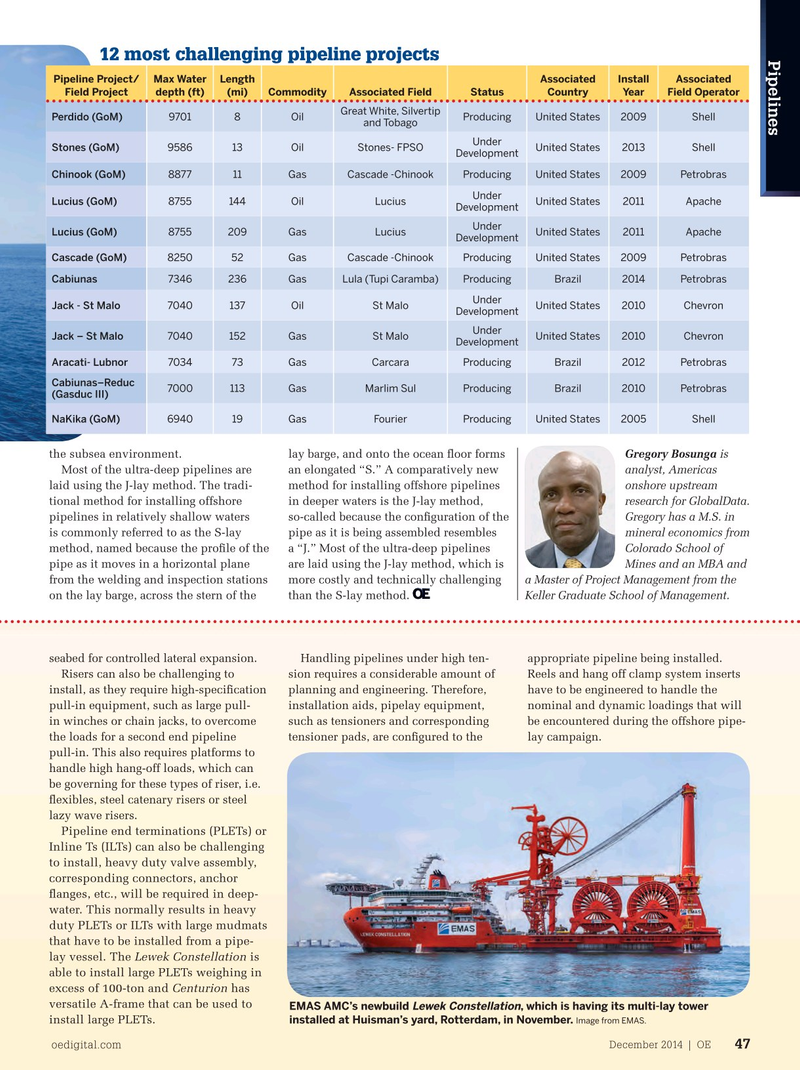
This can be resolved by laying the pipe- duty PLETs or ILTs with large mudmats line in “snake lay,” to reduce the risk of that have to be installed from a pipe- lateral buckling and the size of the expan- lay vessel. The Lewek Constellation is sion jumpers. This can be established able to install large PLETs weighing in with over-bending and under-bending excess of 100-ton and Centurion has the pipelines during pipelay through the versatile A-frame that can be used to reel-lay vessel’s straightener, i.e. inducing
EMAS AMC’s newbuild , which is having its multi-lay tower Lewek Constellation install large PLETs.
pipeline snake lay con? guration on the installed at Huisman’s yard, Rotterdam, in November. Image from EMAS.
December 2014 | OE oedigital.com 47 046_OE1214_Pipelines1and2.indd 47 11/21/14 6:12 PM