Page 96: of Marine News Magazine (November 2016)
Workboat Annual
Read this page in Pdf, Flash or Html5 edition of November 2016 Marine News Magazine
LUBRICANTS protection (see MarineNews, June 2015 edition, page 26). ary, mixed and ? uid ? lm, are presented in Figure 3 for the
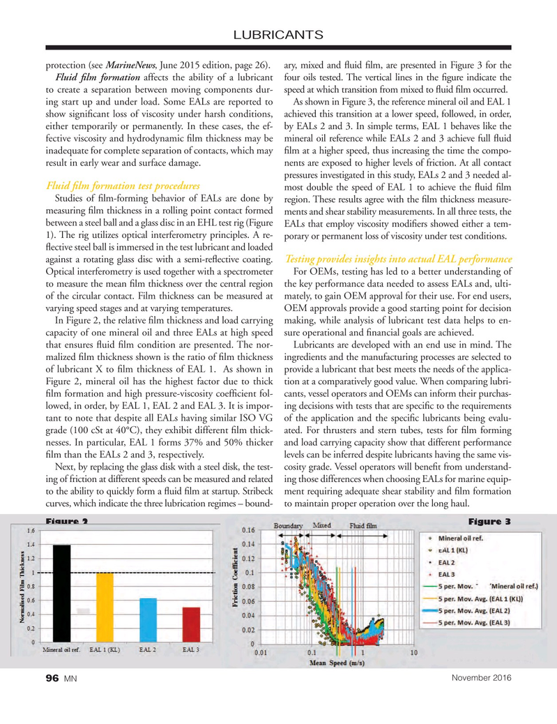
Fluid ? lm formation affects the ability of a lubricant four oils tested. The vertical lines in the ? gure indicate the to create a separation between moving components dur- speed at which transition from mixed to ? uid ? lm occurred. ing start up and under load. Some EALs are reported to As shown in Figure 3, the reference mineral oil and EAL 1 show signi? cant loss of viscosity under harsh conditions, achieved this transition at a lower speed, followed, in order, either temporarily or permanently. In these cases, the ef- by EALs 2 and 3. In simple terms, EAL 1 behaves like the fective viscosity and hydrodynamic ? lm thickness may be mineral oil reference while EALs 2 and 3 achieve full ? uid inadequate for complete separation of contacts, which may ? lm at a higher speed, thus increasing the time the compo- result in early wear and surface damage. nents are exposed to higher levels of friction. At all contact pressures investigated in this study, EALs 2 and 3 needed al-
Fluid ? lm formation test procedures most double the speed of EAL 1 to achieve the ? uid ? lm
Studies of ? lm-forming behavior of EALs are done by region. These results agree with the ? lm thickness measure- measuring ? lm thickness in a rolling point contact formed ments and shear stability measurements. In all three tests, the between a steel ball and a glass disc in an EHL test rig (Figure EALs that employ viscosity modi? ers showed either a tem- 1). The rig utilizes optical interferometry principles. A re- porary or permanent loss of viscosity under test conditions. ? ective steel ball is immersed in the test lubricant and loaded
Testing provides insights into actual EAL performance against a rotating glass disc with a semi-re? ective coating.
Optical interferometry is used together with a spectrometer For OEMs, testing has led to a better understanding of to measure the mean ? lm thickness over the central region the key performance data needed to assess EALs and, ulti- of the circular contact. Film thickness can be measured at mately, to gain OEM approval for their use. For end users, varying speed stages and at varying temperatures. OEM approvals provide a good starting point for decision
In Figure 2, the relative ? lm thickness and load carrying making, while analysis of lubricant test data helps to en- capacity of one mineral oil and three EALs at high speed sure operational and ? nancial goals are achieved. that ensures ? uid ? lm condition are presented. The nor- Lubricants are developed with an end use in mind. The malized ? lm thickness shown is the ratio of ? lm thickness ingredients and the manufacturing processes are selected to of lubricant X to ? lm thickness of EAL 1. As shown in provide a lubricant that best meets the needs of the applica-
Figure 2, mineral oil has the highest factor due to thick tion at a comparatively good value. When comparing lubri- ? lm formation and high pressure-viscosity coef? cient fol- cants, vessel operators and OEMs can inform their purchas- lowed, in order, by EAL 1, EAL 2 and EAL 3. It is impor- ing decisions with tests that are speci? c to the requirements tant to note that despite all EALs having similar ISO VG of the application and the speci? c lubricants being evalu- grade (100 cSt at 40°C), they exhibit different ? lm thick- ated. For thrusters and stern tubes, tests for ? lm forming nesses. In particular, EAL 1 forms 37% and 50% thicker and load carrying capacity show that different performance ? lm than the EALs 2 and 3, respectively. levels can be inferred despite lubricants having the same vis-
Next, by replacing the glass disk with a steel disk, the test- cosity grade. Vessel operators will bene? t from understand- ing of friction at different speeds can be measured and related ing those differences when choosing EALs for marine equip- to the ability to quickly form a ? uid ? lm at startup. Stribeck ment requiring adequate shear stability and ? lm formation curves, which indicate the three lubrication regimes – bound- to maintain proper operation over the long haul.
Figure 2 Figure 3
November 2016
MN 96

 95
95

 97
97
