
Propeller Considerations for Inland River Pushboats
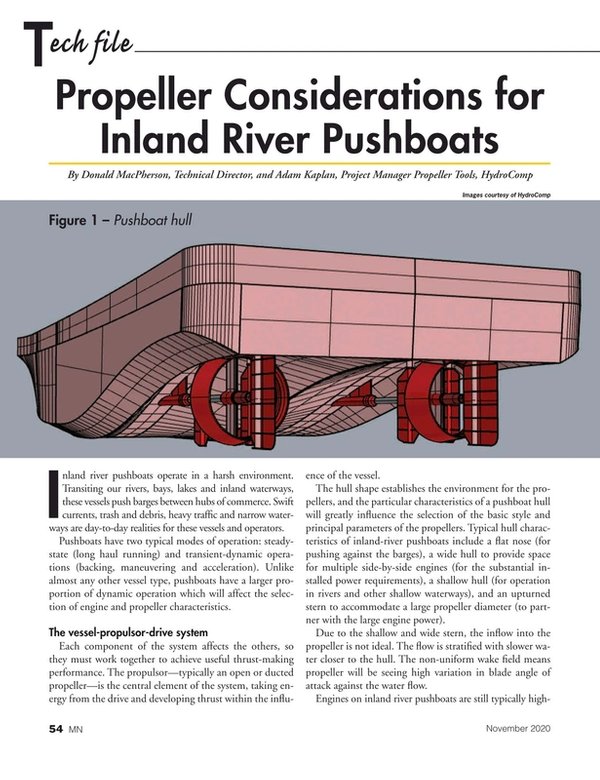
Inland river pushboats operate in a harsh environment. Transiting our rivers, bays, lakes and inland waterways, these vessels push barges between hubs of commerce. Swift currents, trash and debris, heavy traffic and narrow waterways are day-to-day realities for these vessels and operators.
Pushboats have two typical modes of operation: steady-state (long haul running) and transient-dynamic operations (backing, maneuvering and acceleration). Unlike almost any other vessel type, pushboats have a larger proportion of dynamic operation which will affect the selection of engine and propeller characteristics.
The vessel-propulsor-drive system
Each component of the system affects the others, so they must work together to achieve useful thrust-making performance. The propulsor—typically an open or ducted propeller—is the central element of the system, taking energy from the drive and developing thrust within the influence of the vessel.
The hull shape establishes the environment for the propellers, and the particular characteristics of a pushboat hull will greatly influence the selection of the basic style and principal parameters of the propellers. Typical hull characteristics of inland-river pushboats include a flat nose (for pushing against the barges), a wide hull to provide space for multiple side-by-side engines (for the substantial installed power requirements), a shallow hull (for operation in rivers and other shallow waterways), and an upturned stern to accommodate a large propeller diameter (to partner with the large engine power).
Due to the shallow and wide stern, the inflow into the propeller is not ideal. The flow is stratified with slower water closer to the hull. The non-uniform wake field means propeller will be seeing high variation in blade angle of attack against the water flow.
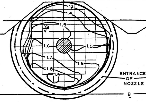 Figure 2 – A stratified wake field; slower water near hull (Image: HydroComp)
Engines on inland river pushboats are still typically high-powered medium-speed diesel engines, although we are seeing the emergence of other drive options. The installed engine power far exceeds the vessel’s own resistance requirements and will be used to generate additional thrust for pushing barges and barge trains. The shape of the maximum power curve is critical to a pushboat’s performance. During steady-state towing and dynamic bollard-like conditions, the propeller will demand all of the power available from the engine, so generous power below rated RPM is essential.
Selection of propeller characteristics
The first decision is typically whether to use an open or a ducted propeller. Ducted propellers are designed for low-speed thrust, where the nozzle becomes a thrust-making contributor. Additionally, the nozzle also helps protect the propeller and provide reduction in wake field variability.
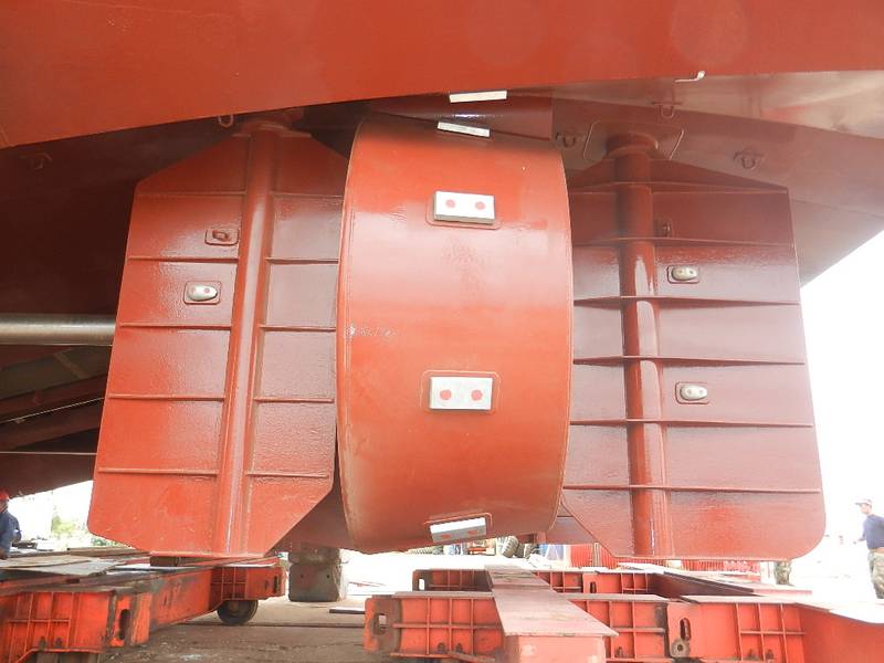 Figure 3 – Nozzle and rudders (Photo: HydroComp)
When part of a well-designed and functioning “propulsor” unit, a nozzle can contribute as much as half of the total unit thrust. However, this contribution is compromised when a portion of the nozzle is blocked, such as when the nozzle is attached via a headbox or is integrated into the hull. This compromise is known as “nozzle effectiveness” and it results in a slight reduction in the inflow velocity into the propeller. The propeller loading will then increase, restoring much of the lost nozzle thrust. However, this redistribution of loading comes with a corresponding increase in power demand. In other words, reduced nozzle effectiveness can be considered a power penalty.
One characteristic of a nozzle that can be modified to increase its thrust-making function at low speeds is its length. Longer nozzles will generate a bit more thrust at low speeds, but will also have a larger “appendage” drag at high speeds (which is not generally critical for pushboat operation).
Once a decision on open versus ducted is in place, we can then focus on the propeller itself. The typical propeller model selection strategies for transit vessels must be modified somewhat for pushboats to account for their dynamic operation (such as backing or maneuvering) and stratified wake field (with variation in blade angle of attack into the flow). For example, propellers for pushboats should avoid anything that would push a blade’s leading edge into a negative angle of attack (and its corresponding potential for damaging face cavitation). This would mean a strong preference for flat-faced propellers instead of propellers with face camber (also called “progressive pitch”). Cupping should also be avoided for the same reason. Further, both cupping and camber also cause a reduction in backing performance.
Propeller sizing and analysis calculations
Sizing and analysis calculations for pushboat propellers require a different set of criteria than those for transit vessels. For example, the prediction of required minimum blade area ratio (BAR) against typical cavitation criteria should include a margin (commonly some 10%) for the frequent dynamic and transient heavy-thrust modes of operation. Blade count is generally selected to mitigate drive-line vibration issues, and four and five blades are common due to BAR requirements.
Unlike transit vessels such as merchant ships or motor yachts, for example, the loading on the propeller will vary day-to-day, as the number of barges and river environment changes. Therefore, a suitable propeller sizing design point for pushboats will be based on matching the propeller’s performance against the engine’s potential maximum power, rather than against the vessel’s thrust requirements. To properly evaluate the delivered thrust capabilities of the system, the calculations should employ what is called a “towpull” analysis that determines the maximum potential delivered thrust for the given engine, driveline and propeller.
Suitable system analysis and propeller sizing tools (such as NavCad and PropExpert) will include appropriate ducted propeller types (ideally with consideration of nozzle length and effectiveness); calculation of pitch, BAR and gear ratio; sizing against engine power with a “torque-identity” option, and calculation of “towpull” that takes the engine’s power curve into account. Propeller design tools (such as PropElements) can include greater detail for optimization of pitch distribution, and a more refined consideration of wake field and nozzle function.
Readers who want to learn more can view a few of HydroComp’s recent recorded webinars for additional information on ducted propellers, pushboats and towpull. These webinars can be found here.
Read Propeller Considerations for Inland River Pushboats in Pdf, Flash or Html5 edition of November 2020 Marine News
Other stories from November 2020 issue
Content
- Interview: John Batten, CEO, Twin Disc page: 12
- Implementing VIDA: The Next Step Forward page: 26
- River Dance: Grounding Triggers Breakaway Barges page: 29
- Historic Dredging Unlocks the Might of the Mississippi page: 32
- US Inland Waterways: High Waters & Swirling Currents page: 44
- There’s Room to Grow on Brazil’s Inland Waterways page: 50
- Propeller Considerations for Inland River Pushboats page: 54
- In Focus: Talking Workboat Safety with AWO's Brian Bailey page: 60