
Underwater Vehicle Propulsion Tech: Tail Shape and Vehicle-Propulsor Performance
Successful underwater vehicle (UV) performance is all about a properly functioning system. The components of a UV’s Vehicle-Propulsor-Drive system are not individual performers. They must be in harmony.
Often overlooked during system design is the relationship between the propeller and the vehicle body, particularly how the water reaches the propeller and – and perhaps even more importantly – how the local pressures between the vehicle and propeller can affect development of useful thrust. This article is intended to give UV vehicle designers and builders a little insight into this critical hydrodynamic interaction.
Propeller pressures
Let’s begin our story by focusing on the propeller. There are two principal pressure zones on either side of a propeller blade that coexist and develop the thrust that moves the vehicle. On the aft side of the propeller is a “positive-pressure” zone (noted as P+ in the graphic). Hold your hand out your car’s window. Slightly rotate your hand to bring your thumb up. As your car moves, air is captured under your hand creating a “positive-pressure”. This is equivalent to the propeller’s aft-most side (its “face”), and it pushes the blades forward.
Simultaneously, there is a suction that is also developed on your hand due to the curvature of the flow that wraps around your thumb and along the back of your hand. (You probably cannot feel this as our hands are not great airfoils, but it is there.) This suction is a “negative-pressure” zone that pulls the blade forward on it forward-side (its “back”). What might be surprising is that for most propellers used on UVs, the suction “negative-pressure” is the principal contributor to propeller thrust.
Vehicle tail shape
So what does this have to do with my upstream vehicle shape? Well, the negative propeller suction can have influence at quite some distance. Not only will this suction zone pull in water to the propeller, but it also pulls back on the hull or vehicle body in front of it. This sacrificial pulling back of the vehicle can be effectively considered as an added drag, but more often it is dealt with as a system “thrust deduction”. And vehicles that have a rearward-facing shape that is close to the propeller are particularly susceptible to thrust deduction losses.
The graphic shown here illustrates three different tail shapes frequently seen on contemporary “body-of-revolution” or “torpedo-like” UVs. Let me first acknowledge that hydrodynamics can indeed take a back seat to other design constraints, such as a prescribed maximum body diameter or length. That said, the UV design process will always achieve better outcomes when the consequences of body shape decisions are understood by designers. So to that end, there are four principal shape characteristics that we want to identify during design – 1) the slope of flow into the propeller, 2) the curvature of the transition from the main cylindrical body to the propeller, 3) the distance between the propeller blade and the upstream body, and 4) the ratio of the propeller diameter to body diameter.
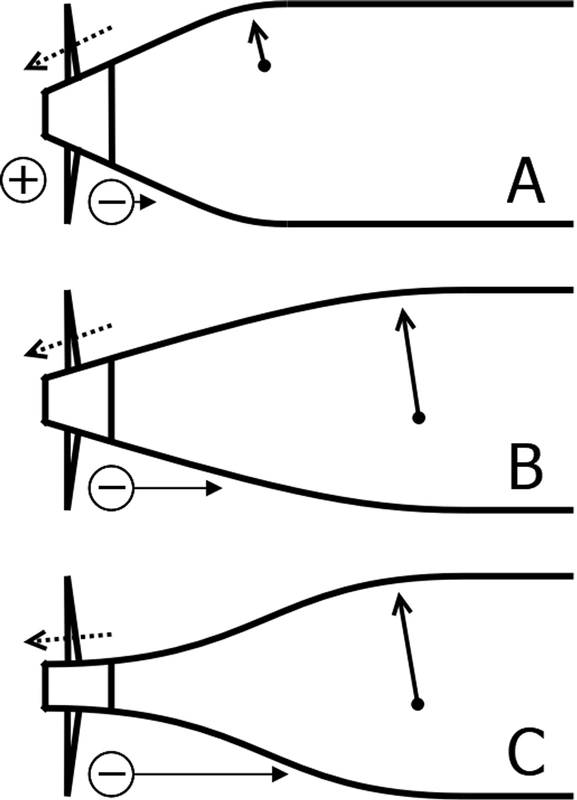 Image: Hydrocomp
Slope of flow into the propeller
A propeller ideally wants inflow that is as axial as possible. The reasons for this are partly hydrodynamic and partly practical. There is a natural hydrodynamic compression and increase in velocity as water passes through a propeller. If the local environment further enhances this compression with a (more-or-less) conical inflow slope angle, we get a lot of convergence of water aft of the propeller leading to energy losses, cavitation, and hydroacoustic noise from a strong hub vortex.
The practical considerations are actually due to a limitation in most propeller design tools, which are based on axial inflow. Special codes are needed that allow for conversion of the blade section foil geometry from circular to conical coordinate system.
We can see how tail slope angle is (A) very steep with a short tail section, (B) reduced as the tail is lengthened, and (C) becomes nicely axial when the local tail shape is inflected into the propeller hub. (An inflected tail can also often provide the added benefit of a smaller hub.)
Curvature at the transition shoulder
Let me encourage you to “think like the water” when considering all things hydrodynamic. Let’s say that you are a particle moving along a cylindrical body and you come upon a need to alter your direction because the body is narrowing. Your momentum wants you to continue your axial path, but as pressure is lowered with the contraction, you are encouraged to follow the body. Now, if your momentum is strong enough or the curvature is tight enough, you cannot stay attached to the body and flow separation occurs. There is nothing good that comes with flow separation on a UV body. (Separation is appropriate in other circumstances, such as high-speed planing or super-cavitating propellers, but not in the UV world.)
We have developed some in-house design guidelines to help quantify curvature thresholds, but in general less is always better. Curvature is (A) often too tight with a short tail length, but (B and C) softer and more flow-friendly with a longer tail.
Axial distance from blade to body
This parameter is the principal contributor to a high “thrust deduction”. The influence of the propeller’s “negative-pressure” zone lessens with distance, allowing more of the propeller’s thrust to be effectively used to overcome the resistance of the UV. How much more? Thrust deduction losses can be quite small (close to zero) with adequate distance to more than 20% for short and steep tail sections. For example, a US Navy research study [1] showed how increasing the axial distance from approximately 0.3 to 0.7 body diameters reduced thrust deduction by half for a recovery of nearly 8% lost thrust. (The measurement was taken axially from the blade’s 80% radius to the body at the same radial position.)
Axial distance is (A) quite close with a short tail section with a steep tail slope angle, (B) naturally greater with a longer tail section, and (C) can be pushed even further forward with an inflected shape.
Propeller-to-body diameter ratio
This simply describes that a smaller diameter propeller will have the thrust-making part of the blade closer to the vehicle body, with a corresponding increase in the thrust deduction influence. The magnitude of influence varies with the type of tail section, of course, but in round terms we would expect to see a doubling in thrust deduction when the propeller diameter is reduced from 100% to 50% of the body diameter.
Calculation methods and design tools
Prediction of thrust deduction for body-of-revolution UV vehicles is being addressed by new capabilities in HydroComp’s NavCad® software. A new development initiative to better support UV designers started with an update for the data definition of nose, mid, and tail geometries. This allowed for implementation of new drag prediction methods, as well as for the hull-propulsor coefficients of wake fraction and thrust deduction. Coming late in 2020 is new support for electric motor drivelines with a proprietary partial load motor efficiency prediction capability. Now UV designers can reliably predict current draw, electrical input power, and overall motor efficiency for all operational speeds and conditions.
Of course, more complex computations may be justified for specific body design projects. In addition to engineering services for specialized UV hydrodynamic analysis and propulsor design, HydroComp is also developing a reduced-order analytical flow code for NavCad to provide design prediction of body pressures, hull form drag, boundary layer velocity distribution, and thrust deduction. We are also leading an effort to support designers with a pipeline for the use of CFD in UV body design. Working with other software developers, we are establishing best practices for the integration and use of NavCad’s UV modules with naval architectural software and CFD codes, as well as to provide corresponding guidance, training, and professional development to the UV community.
[1] Huang, T.T., et al., “Propeller/Stern/Boundary-Layer Interaction on Axisymmetric Bodies: Theory and Experiment”, DTNSRDC Report 76-0113, 1976
About the Author
Donald MacPherson is Technical Director of HydroComp, Inc., a research consultancy specializing in applied hydrodynamic and propulsion system simulation. Widely regarded as one of the industry’s foremost experts in analytical prediction methods for the performance of marine vehicles and propulsors, he oversees all software product development and is principal investigator for engineering services. A graduate of Webb Institute, Don is a Fellow of the Society of Naval Architects and Marine Engineers, and member of its Propeller Hydrodynamics and Underwater Noise panels.
Read Underwater Vehicle Propulsion Tech: Tail Shape and Vehicle-Propulsor Performance in Pdf, Flash or Html5 edition of July 2020 Marine Technology
Other stories from July 2020 issue
Content
- Underwater Vehicle Propulsion Tech: Tail Shape and Vehicle-Propulsor Performance page: 16
- Charting Terradepth's Big Ambitions in the Unmanned Vehicle Space page: 20
- Interview: RDML Gallaudet Steers NOAA’s Path Toward Uncrewed Maritime Systems page: 26
- Subsea Technology and the New Routes to Residency page: 38
- Hacking 4 Environment: Oceans - Creating Entrepreneurs from Scientists and Students page: 46
- Tracking Climate Change onboard SeaExplorer page: 50