The M/S Boogabilla
The recently completed M/S Boogabilla is classed by its builders and owners as the third generation of deepsea roll-on/roll-off vessels. The ship incorporates several new items for this type of vessel, such as a largebore, slow-speed diesel engine; three parallel trafficways, and a jumbo angled stern ramp.
The Boogabilla was designed and built by Mitsubishi Heavy Industries, Ltd. at its Koyagi Works of Nagasaki Shipyard for Scan Carriers, under contract by Transatlantic Reederi. The owner's unique ro/ro service requirements also were integrated into the design.
The vessel has four cargo decks consisting of tank top (deck 1), weather deck (deck 4) and two in-between decks. A hoistable cardeck in the cargo space below deck 3 and two tiers of hoistable and partly fixed cardecks at the forward part of deck 3 are also provided. A large quarter stern ramp, designed for a total load of 400 tons, is fitted at the stern end of deck 3, from which cargoes are loaded or unloaded and distributed to other decks through onboard rampways.
The machinery space and accommodations are located aft. Deck 4, below the accommodations, also is utilized as a cargo space. A funnel for the engine exhaust is located on the starboard side aft and is also used as the stern-ramp post. In order to obtain additional versatility, breakbulk refrigerated cargo spaces and tallow-oil tanks are provided in the aft part of deck 2 and the forward end of the cargo spaces respectively.
Cargo spaces, including the weather deck, are designed and equipped with a complete stowage pattern for containers. However, the capacity for carrying all kinds of general cargo was pronounced in the design criteria.
All decks have neither sheer nor camber. Clear deck heights for cargo loading and other design conditions are: deck 1—10 feet 6 inches; deck 2—20 feet 8 inches; deck 3—20 feet 8 inches, and deck 4—17 feet 8M> inches (below deck 5) and elsewhere 20 feet 8 inches.
Fifty tons of axial load with six wheels, assuming fork lifts with a 20-foot container, a trailer loaded with two 20-foot containers, LUF trailer loaded with eight 20-foot containers and 150 tons payload wagon also were considered as design conditions. In addition, the aft section of deck 3 is specially reinforced to load heavy cargo.
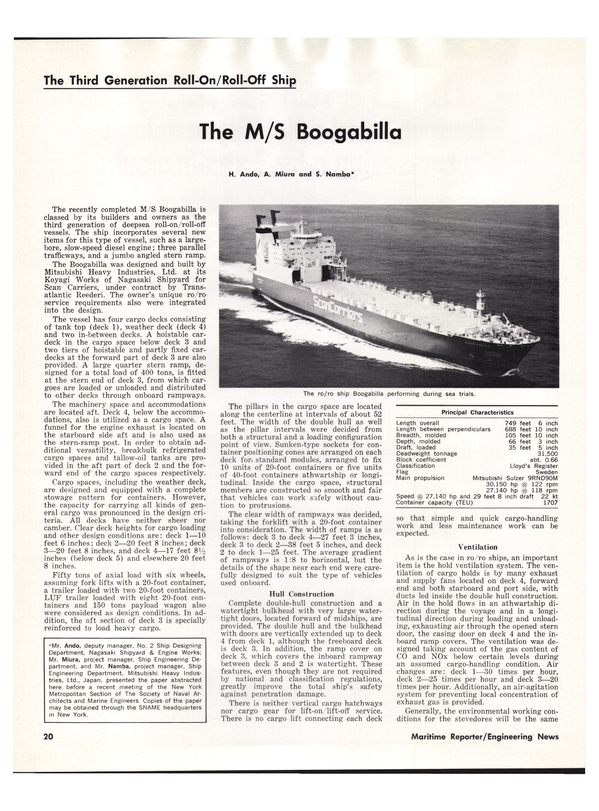
The pillars in the cargo space are located along the centerline at intervals of about 52 feet. The width of the double hull as well as the pillar intervals were decided from both a structural and a loading configuration point of view. Sunken-type sockets for container positioning cones are arranged on each deck for. standard modules, arranged to fix 10 units of 20-foot containers or five units of 40-foot containers athwartship or longitudinal.
Inside the cargo space, structural members are constructed so smooth and fair that vehicles can work safely without caution to protrusions.
The clear width of rampways was decided, taking the forklift with a 20-foot container into consideration. The width of ramps is as follows: deck 3 to deck 4—27 feet 3 inches, deck 3 to deck 2—38 feet 5 inches, and deck 2 to deck 1—25 feet. The average gradient of rampways is 1:8 to horizontal, but the details of the shape near each end were carefully designed to suit the type of vehicles used onboard.
Hull Construction Complete double-hull construction and a watertight bulkhead with very large watertight doors, located forward of midships, are provided. The double hull and the bulkhead with doors are vertically extended up to deck 4 from deck 1, although the freeboard deck is deck 3. In addition, the ramp cover on deck 3, which covers the inboard rampway between deck 3 and 2 is watertight. These features, even though they are not required by national and classification regulations, greatly improve the total ship's safety against penetration damage.
There is neither vertical cargo hatchways nor cargo gear for lift-on/lift-off service.
There is no cargo lift connecting each deck so that simple and quick cargo-handling work and less maintenance work can be expected.
*Mr. Ando, deputy manager, No. 2 Ship Designing Department, Nagasaki Shipyard & Engine Works; Mr. Miura, project manager, Ship Engineering Department, and Mr. Namba, project manager, Ship Engineering Department, Mitsubishi Heavy Industries, Ltd., Japan, presented the paper abstracted here before a recent meeting of the New York Metropolitan Section of The Society of Naval Architects and Marine Engineers. Copies of the paper may be obtained through the SNAME headquarters in New York.
Ventilation As is the case in ro/ro ships, an important item is the hold ventilation system. The ventilation of cargo holds is by many exhaust and supply fans located on deck 4, forward end and both starboard and port side, with ducts led inside the double hull construction.
Air in the hold flows in an athwartship direction during the voyage and in a longitudinal direction during loading and unloading, exhausting air through the opened stern door, the casing door on deck 4 and the inboard ramp covers. The ventilation was designed taking account of the gas content of CO and NOx below certain levels during an assumed cargo-handling condition. Air changes are: deck 1—30 times per hour, deck 2—25 times per hour and deck 3—20 times per hour. Additionally, an air-agitation system for preventing local concentration of exhaust gas is provided.
Generally, the environmental working conditions for the stevedores will be the same on all decks although there are a different number of air changes per hour. It is not sufficient to use the number of air changes as a design criteria, and consequently new criteria was developed and used for this vessel.
As to fire protection for cargo holds a smoke-detecting system, gas-detecting system and carbon-dioxide fire-extinguishing system are provided. The carbon dioxide system is of the low-pressure type and has a quantity corresponding to 45 percent of the largest compartment. Two-thirds of the gas capacity can be discharged within 10 minutes so as to meet IMCO's latest recommendations.
Hydrodynamic Design To fulfill the basic characteristics of the vessel, such as, geometrical configurations, deadweight, ship's speed, trim and stability and precautions for vibrations, ship's hull form was carefully developed on the basis of extensive builder's experience and investigations in this field.
As the ship's breadth and draft were given by the owner from the cargo handling and operation point of view, the ship's length was the only variable parameter in the optimization of the ship's dimension. After parametric studies of variation in ship's length, block coefficient and required power of the main engine, a ship's length of 688 feet 10 inches was selected.
So as to obtain an optimum hull form, five kinds of hull forms were tested. Starting with the original hull form designed on the basis of existing data, investigations were made into the effect of size and shape of bulbous bow, load waterline and frame line shapes.
The aft body lines were very carefully designed to minimize the propeller exciting forces with an improved wake distribution and frame lines as well as for obtaining a good performance of ship's speed. The difficulty of the design of the aft body consisted of resolving inconsistent demands.
Full breadth was required even at the aft end, and the draft was shallow compared with the breadth and the higher main engine power (larger propeller diameter).
Safety Measures Various safety measures have been adopted at the owner's request.
The rampway between deck 3 and deck 2 is covered by a watertight ramp cover, dividing the vessel into two compartments horizontally. The cover is designed to have watertightness with flooding above or below deck 3. Bilge suction lines from deck 3 are directly led to the engine room. These lines are separated from those from deck 1.
Eight sets of freeing ports with valves with a l^/a-inch diameter are arranged on the side shell just above deck 3. The valves can be remotely controlled from the deck control room with hydraulic devices. These freeing ports are provided for releasing the water directly overboard.
A watertight bulkhead with very large watertight doors is arranged between the decks from deck 1 to deck 4, on a vertical line, in order to divide the cargo space into two compartments veritcally. These doors were carefully designed and arranged not to interfere with the requirements for easy cargo handling.
Pipe passages on both sides on deck 1 are cross-connected at the forward end, which enables the list of the vessel to be smaller automatically when one side passage is damaged.
Double-hull construction was provided from deck 1 up to the weather deck, although deck 3 is designated as the freeboard deck. This construction makes the inner surface flat which enables rapid cargo handling and also makes the ship safer. The double hull between deck 3 and deck 4 contributes to the adjustment of the rolling period in ballast conditions by providing ballast-water tanks as well as increasing the residual buoyancy and residual BM when full vertical penetration should occur.
Each ventilating duct from the cargo spaces was fitted with a watertight damper on the top of the fan, which is remotely controlled from the deck control room. It prevents the air from flowing out freely and makes the flooding time longer when the cargo space is flooded, as well as acting as a fire damper.
All ventilating ducts for cargo spaces are independently led from the weather deck to each deck concerned and the ducts are led with triple hull construction below the freeboard deck to avoid direct flooding into the cargo spaces from a small damage to the outer shell.
Escape trunks are arranged from the cargo spaces to the weather deck through the double-hull construction and a watertight door is provided on every entrance to the trunk to avoid free connection between each deck space and also to avoid direct flooding into the cargo spaces by damage to the outer shell.
No side port opens directly into the engine room or cargo space below the freeboard deck. This concept avoids eventual flooding from the side port when it is opened or damaged.
Design Items One of the main points of the vessel is the installation of a slow speed diesel engine (Mitsubishi Sulzer 9RND90M rated at 30,150 hp maximum and 27,140 hp normal rating, 122 rpm and 118 rpm respectively) for propulsion.
Generally, the slow-speed diesel engine is advantageous due to the lessened fuel costs of heavy fuel oil, lower lubricating-oil consumption, and less maintenance due to the smaller number of cylinders. However, the engine height required for overhauling is a major disadvantage for ro/ro arrangements.
This problem was studied together with the machinery room arrangement and the inboard traffic arrangement. The machinery is arranged within the limited space incorporating the main engine, four diesel alternators, engine control room, work shops and many tanks as well as all the usual auxiliaries.
The engine room length is 110 feet 3 inches.
The exhaust trunking from the main engine and the auxiliaries are horizontally led to the starboard side and up to the offset funnel which is also used as the stern ramp post.
One side thruster is installed at the bow and one at the stern.
Three traffic lanes on the aft end of deck 3, consisting of an upward rampway to deck 4, a downward rampway to deck 2 and a horizontal way to deck 3 forward, are arranged in parallel just above the engine room. This arrangement was required from a cargo-handling point of view. The solution was attained by arranging the upward rampway at the ship's center so that the space below could be utilized to install the diesel engine.
A very big fixed quarter-type stern ramp with a separate weathertight stern door is the third special item. The access at the aft end of deck 3 is 86 feet 7 inches wide and 22 feet high. The height of deck 3 above the baseline at the stern, that is the "threshold height" is 47 feet 7 inches. The height of the kingpost for supporting the ramp is about 158 feet above the baseline.
In order to make this arrangement feasible, together with a wide stern access, the full breadth of the ship had to be extended to almost the aft end on deck 3.
In addition, ro/ro ships generally have a tendency to trim by the stern due to cargo and lightweight distribution, consequently the longitudinal center of buoyancy has to be located further aft than on ordinary cargo ships.
Mitsubishi Heavy Industries, Ltd., at the time of delivery of this special vessel, acknowledged that without the extensive cooperation rendered by the owner, regulatory bodies, subcontractors, and all peopie concerned with the initial design, detail design, research and experiments, approval of the design, procurements of many components, fabrication at site, tests and inspections, etc.
this project would not have been as successful as it has been.
Read The M/S Boogabilla in Pdf, Flash or Html5 edition of December 1978 Maritime Reporter
Other stories from December 1978 issue
Content
- Agreement In Principle Announced On U.S.-U.S.S.R. Marine Insurance page: 4
- Veritas Guide Shows Docking Facilities For 200,000-DWT Ships page: 4
- M/S Yulius Fuchik, First Of Two Valmet-Built Lykes SEABEE-Type Barge Carriers For USSR page: 7
- Davie Shipbuilding Signs License Agreement For Gaz-Transport LNG Containment System page: 7
- Vaporphase To Supply Systems For Four New USCG Cutters page: 7
- J.J. Henry Co., Inc. Promotes Victor Chen page: 7
- Genstar And British Shipbuilders To Bid For CAF Patrol Frigates page: 7
- Bethlehem Steel Corp. Elects Anthony St. John page: 8
- USCG Contract For Oil Spill Pumps To Offshore Devices, Inc. page: 8
- Artemis Marine Amends Application For Catug Title XI Guarantee page: 9
- Livanos Elected To ABS Management Committee page: 9
- 1978 SNAME Annual Meeting Cites Role In Maritime Industry Progress page: 9
- Theriot And Mitsui Form THERIOT-MODEC Enterprises, Inc. page: 10
- Adams & Porter Associates Names Glotfelty And Currie page: 10
- Jardine Offshore Promet To Construct Paceco Equipment Under License In Singapore page: 10
- American Bureau Of Shipping Moves Its Headquarters To 65 Broadway In New York City page: 11
- MarAd Amends Two Research Contracts page: 12
- George E. Chronakis Joins Electro-Nav page: 12
- Ship Structure Committee Publishes Two Reports On Strength Of Materials page: 12
- Kenneth M. Jones Elected President Offshore Logistics, Inc. page: 12
- J. Ray McDermott & Co. Elects Eight Officers page: 13
- L N G - L P G Conference Set For Houston, Texas November 13-16, 1979 page: 13
- A g r i - T r a n s Elects Paul J. Staadeker VP Transportation page: 14
- Arnessen Corporation A p p o i n t s Stephen Keller page: 14
- Sun Ship Awarded $137.5 Million To Build Two Ships For Waterman page: 14
- Delaval Turbine Wins $20-Million Contract To Power New Cargo Fleet page: 15
- Farboil Introduces STA-CLEAN Coating page: 15
- Congressional Coalition To Seek Solutions To Shipyard Problems page: 16
- Halter Marine Delivers Supply Boat To Brazil page: 16
- Port Weller Awarded $10-Million Conversion page: 16
- IMODCO Establishes Far East Marketing Office page: 16
- G.A. Watkins To Head Global Transport's International Division page: 17
- General Dynamics7 Innovative Method Of Launching Submarines page: 17
- Mobil Oil Corporation Names Harmon Hoffmann And Walter C. Mink Jr. page: 18
- Bird-Johnson Opens Washington, D.C. Office page: 18
- Seaward, Inc. Promotes Michael K. Kutzleb page: 18
- Union Mechling Corp. Names Ronald Olander page: 18
- Selby, Battersby & Co.'s N e w Flooring C o m b i n e s U n i q u e S a f e t y Features page: 19
- The M/S Boogabilla page: 20
- Amerada Hess To Build Five Catug Units At Cost Of $283,800,000 page: 20
- J.J. Henry Co., Inc. Names Gerald Jones Manager Portsmouth, Va. Office page: 20
- Dredge Technology Announces Contracts page: 22
- Worthington Compressors Names Hands President page: 22
- Savannah Machine And Shipyard Awarded $2.6-Million Contract page: 22
- Reno Spiteri Opens O f f i c e In M a l t a page: 23
- A r g o N a m e s Nietsch To Pollution Control Post page: 23
- GE Credit Buys 188,500-DWT Tanker For $84.9 Million page: 24
- Patrick J. Marcello Elected Vice President Moran Shipping Agencies page: 25
- Extensive Line Of Industrial Tachometers Described In New Catalog page: 25
- ITT Mackay Marine Hosts Product Display And Discussion On Key Marine Communication And Navigation Issues page: 25
- Pacific Northwest Section, SNAME, Holds Annual Meeting In Union, Washington page: 26
- First Heavy Lift Ships Built In U.S. page: 27
- Nickum & Spaulding Completes Design Of Crab Boat For Operation In Bering Sea page: 27
- SeaTec International Appoints Samuel Rugh page: 27
- London To Host Two-Day Conference On Ship Propulsion page: 27
- Stevedoring Companies Cited For Reducing Accidents On Piers page: 28
- MSC Seeks Bids To Operate Five Tankers page: 29
- Institute Of Marine Engineers Hears Guest Speaker From BP Tanker Company, Ltd. page: 30
- New $20-Million Jackup Built By Marathon LeTourneau Placed In Service By Fluor page: 30
- ASNE Long Beach-Greater Los Angeles Section Discusses Corrosion Protection And Control page: 30
- El Paso Savannah Christened At Avondale Shipyards In New Orleans Joins A Fleet Of Nine LNG Tankers page: 30
- Major Changes Prompted By Magnavox Division Growth page: 31
- AWO Spokesman Views User Tax Bill With Cautious Anticipation page: 32
- Moore McCormack Bulk Transport, Inc. Names William Crossman page: 32
- Sixth International LNG Conference Invites Proposals For Papers page: 32
- Crowley Environmental Services Appoints Operations Supervisor page: 32
- SNAME California Sections Hold Annual Joint Meeting page: 32
- Fourth Chesapeake Sailing Yacht Symposium Set For January 20 page: 34
- Avondale Shipyards' New Pipe Fabricating Facility page: 34
- American Steamship Company Elects Three Executives To Vice Presidential Posts page: 37
- Zapata Commissions Latest Of Workboats Supporting Atlantic Coast Exploration page: 37
- Bird-Johnson Appoints Green To Great Lakes, Nielson To Gulf Coast page: 38
- New 500-Ton Crandall Railway Drydock For Fairhaven, Massachusetts page: 38
- Allweiler Pump Opens Office In United States page: 39
- MarAd Report Forecasts Bunker Fuel Prices page: 39
- SNAME Scholarships For Graduate And Undergraduate Levels page: 39
- MarAd Awards Contracts To Study Port Needs In Alaska, Hawaii, Oregon page: 40
- lotron Corporation Merges With Varo, Inc. page: 40
- Tidewater Sending Ten Additional Vessels To Work Offshore Mexico page: 41
- New England Sections Of ASNE And MTS Discuss Submersibles page: 41
- Peterson To Build Ferry For Washington Island Ferry Line page: 41
- Texas Gas Transmission Executive Honored At Towboat Christening page: 42
- ASNE Southern New England Section Discusses Southeastern Connecticut's Stake In The Development Of Offshore Resources page: 42
- Joseph L. Waldvogel Joins Soros Associates page: 42
- De Laval Issues Comprehensive Brochure On Centrifugal Separators page: 42
- Foreign Nations Urged To Crack Down On Soviet Rate-Slashing page: 42
- Manlift For Hazardous Environment Announced page: 44
- New MIPCO Brochure Describes Full Line Of Reefer Power Systems page: 44
- SNAME Gulf Central Section Hears Paper On Underwater Welding At Annual Fall Meeting page: 47
- Louis L. Frierson Elected President George Engine Company page: 47
- Crowley Subsidiary TMT Orders 400 Specialized Truck Trailers page: 52
- John Kuchta Joins Gulf Mississippi Marine Corporation page: 53
- American Abrasive Metals Develops New Non-Slip Coating For Marine Use page: 53
- Krogen Designs Landing Craft Built By Lantana Boatyard For Alaskan Service page: 54
- New Appointments At Bailey Group page: 54
- John Cassedy Urges Congress To Stem Tide Of Soaring Liability Awards To Seamen page: 58
- The Inverto Marine Bilge And Ballast Water Separator page: 58
