Fluid Dynamics
-
- VSP: Same Power, 9% More Bollard Pull Maritime Reporter, May 2004 #35
With the commissioning of the Norway's Bukser og Berging Voith Water Tractor Baut. the improved characteristics of the new Voith Schneider Propeller (VSP) blades were demonstrated. The bollard pull — as supervised by DNV — was improved by nine percent while using the same input power.
The VSP is designed to provide accurate, stepless and extremely swift thrust variations in accordance with XY coordinates. In order to improve the hydrodynamic characteristics of the VSP further, a new generation of blades has been developed. The basis for the successful development is the numeric simulation of the fluid dynamics (CFD = Computational Fluid Dynamics). The CFD method initially serves to optimize the shape of the propeller blade; it also provides the exact loads for the structural and mechanical optimization by using the Finite Element Method (FEM).
The new VSP blades for the propeller size 36R6/255- 2 represent an important step towards the further improvement of the hydromechanics of Voith Schneider Propellers.
For new propellers, the new profiles will be standard; any further improvements can be realized with immediate effect. Voith, founded in 1867. has a long history in the marine propulsion field. With 24,000 employees and annual sales of about $3 billion, it is one of the largest of Europe's family-owned companies.
Circle 1 on Reader Service Card Below: A CAD illustration of the new VSP size 36R6/255-2 with a propeller input power of 3380kW.
Top Right: Blade after machining.
-
- Advanced Simulation Helps to Solve Ballast Water Management Problems Maritime Reporter, Feb 2013 #18
Ballast water management poses problems in design and operation of ships. Computational fluid dynamics (CFD) offers solutions with design, type approval and trouble-shooting. Computational fluid dynamics (CFD) denotes collectively techniques for solving equations describing the physics of fluid flow.
-
- Vosta LMG Delivers New Dredge Ball Joints Maritime Reporter, Aug 2014 #119
The Crossover ball joint from Vosta LMG is a new dredge ball joint that is designed to provide optimal flow performance. Through computational fluid dynamics (CFD) the frictional losses and turbulence have been reduced. Conventional dredge ball joints act like a ball valve when tilted, causing the flow
-
- Navy Tests Scale Models in Big Facilities Marine Technology, May 2018 #28
capability at Carderock.A significant amount of testing is conducted before coming to the LCC. “We can do our computer modeling of the computational fluid dynamics, then build a physical model to test in our tow tank. Then we can test that model, or a larger one, in the LCC. Eventually, our signatures department
-
- Revolutionizing Deepwater Drilling Riser Buoyancy Marine Technology, Apr 2017 #32
. Extensive engineering design work is now performed using specialized software to produce local and global finite element (FE) and computational fluid dynamics (CFD) analysis to develop optimum designs. The ability to model equipment and system responses to environmental forces helps advance product development
-
- BMT Fluid Mechanics to Validate FLNG Design Maritime Reporter, Oct 2015 #60
of BMT Group. Suba highlights the unique safety concerns which need to be considered and provides insight into the benefits of using Computational Fluid Dynamics (CFD) to complement physical modelling through Wind Tunnel Testing and ensure oil and gas operators have confidence that the design is fit for
-
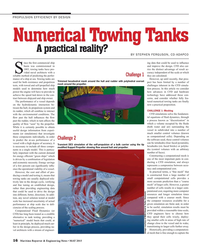
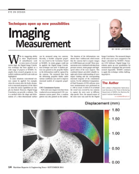
- Numerical Towing Tanks A Practical Reality? Maritime Reporter, May 2015 #16
solution tested at model scale has increased uncertainty of actual performance at ship scale due to deficiencies of the scaling process. Computational Fluid Dynamics (or CFD) has long been touted as a credible alternative to tank testing, providing a “numerical” model basin that could, at least in principle
-
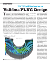
- MN 100: All American Marine, Inc. Marine News, Aug 2015 #10
Guidelines (NVIC 9-97 Ch-1). The catamaran features an advanced hull shape that was custom designed using digital modeling and Computational Fluid Dynamics (CFD) analysis testing. CFD hull optimization led to savings of nearly 20 percent power. The hull design is complemented by Teknicraft’s signature
-
- LNGreen: Next-generation LNG Carrier Concept Maritime Reporter, Aug 2015 #74
, machinery and system configuration. These developments were based on DNV GL’s integrated systems engineering approach COSSMOS, computational fluid dynamics (CFD) calculations, and a containment system design, tailored to a specific operational profile and anticipated trades. HHI and DNV GL carried
-
- MN100: Bristol Harbor Group, Inc. Marine News, Aug 2016 #10
with the USACE is the design of a wicket lifting vessel for operation at the Olmsted Lock & Dam on the Ohio River. Extensive use of both Computational Fluid Dynamics (CFD) and Finite Element Analysis (FEA) was incorporated in the design process to ensure that the vessel is capable of performing the necessary
-
- Navatek Launches Innovative Tech Demonstrator Craft Maritime Reporter, Jul 2003 #24
on an earlier, small-scale 65-ft., 50 LT Navatek lifting body demonstrator craft called M1DFOIL. as well as through extensive computational fluid dynamics (CFD) studies. A former U.S. Navy Surface Effect Ship (SES-200) provided the parent hull of the HYSWAC, reducing project costs. During the
-
- SNAME President Names Committee Chairmen Maritime Reporter, Mar 15, 1977 #23
emeritus, Webb Institute of Naval Architecture, Glen Cove, N.Y. Committee on Journal of Ship Research — chairman, Ralph D. Cooper, head, Fluid Dynamics Program, Office of Naval Research, Department of the Navy, Arlington, Va. Committee on Marine Technology — chairman, E. Scott Dillon, consultant
-
 )
June 2024 - Maritime Reporter and Engineering News page: 38
)
June 2024 - Maritime Reporter and Engineering News page: 38, locations, sizes, and In this paper, we delve into the key role that Computational fow rates can all be adjusted until an optimal ventilation ar- Fluid Dynamics (CFD) analysis plays in optimizing vessel rangement is found. ventilation systems. By leveraging advanced simulation tech- In ship design, the
-
 )
Jan/Feb 2024 - Marine Technology Reporter page: 4th Cover
)
Jan/Feb 2024 - Marine Technology Reporter page: 4th Coverhelp you accomplish your mission: Hurricane Intensity Mapping; Marine Mammal Tracking and Mitigation, Biological & Ecological Monitoring; Under-ice Fluid Dynamics. www.teledynemarine.com MTR JanFeb2024 Covers 2,3 and 4.indd 3 1/18/2024 9:09:40 A
-
 )
January 2024 - Maritime Reporter and Engineering News page: 14
)
January 2024 - Maritime Reporter and Engineering News page: 14incredible 68 meters tall. delved into the forefront of Computa- launch site, so it will spend most of its Today’s largest OceanWings are 37 tional Fluid Dynamics (CFD) advance- life on a ? xed trans-Atlantic route be- meters tall with a projected area of 363 ments, encompassing the detailed mod- tween
-
 )
January 2021 - Maritime Reporter and Engineering News page: 36
)
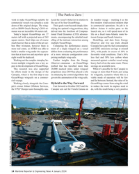
January 2021 - Maritime Reporter and Engineering News page: 36REPAIR & CONVERSION RV Roger Revelle & Ef? cient Re? t by Design From 3D laser scanning to Computational Fluid Dynamics, an ef? cient and successful major mid-life re? t such as the one completed on the RV Roger Revelle requires intricate advance design planning, an updated technical toolbelt, as well
-
 )
September 2020 - Maritime Reporter and Engineering News page: 53
)
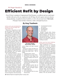
September 2020 - Maritime Reporter and Engineering News page: 53lift-to-drag ratio to NASA. Through the use of complex with a “dedicated” design for Zero versus a standard ? n means that there is Computation Fluid Dynamics (CFD) Speed and underway performance with less impact to vessel speed and reduced calculations, the shape of the Dyna-Foil a retractable feature
-
 )
August 2019 - Marine News page: 40
)
August 2019 - Marine News page: 40provide the very best in propellers and hydrodynamic engineering for Amer- ica’s working ? eet. The ? rm utilizes state-of-the-art Com- putational Fluid Dynamics (CFD) software in conjunction with decades of experience to deliver class-leading service to a long list of repeat clients. The engineered designs
-
 )
August 2017 - Marine News page: 82
)
August 2017 - Marine News page: 82projects. inland rivers with a rated horsepower of 6,600 HP using Shock Mitigation’s RIB & High Speed Craft Directory triple Z drives, Computational Fluid Dynamics (CFD) is an online resource that brings together equipment and analyses was used in the design to provide increased ef- new technology.
-
 )
May 2017 - Marine News page: 53
)
May 2017 - Marine News page: 53tug, three RApide 2000-Z2 class port-assist pusher tugs, and 64 jumbo hopper barges. During the early phases of design, extensive Computational Fluid Dynamics (CFD) simula- tions were used to optimize the hull shapes to minimize total convoy resistance. In all cases, the z-drives are ? tted in customized
-
 )
April 2017 - Maritime Reporter and Engineering News page: 30
)
April 2017 - Maritime Reporter and Engineering News page: 30renewable energy platform speci? cally on-board data collection, analysis using Computational designed for shipping. Aquarius MRE is an integrated Fluid Dynamics (CFD) software and virtual wind tun- renewable energy system for ships that incorporates En- nel simulations. Computer modeling of ships ? tted
-
 )
December 2016 - Maritime Reporter and Engineering News page: 36
)
December 2016 - Maritime Reporter and Engineering News page: 36by mized ship condition and to enhance the vironmental guidelines such as fuel oil mon Structure Rule. The vessel features CFD(Computational Fluid Dynamics).” fuel ef? ciency. The vessel has six pairs protection, Inventory of Hazardous Ma- a double side skin and has a ? ush deck, Electric power
-
 )
August 2016 - Marine News page: 10
)
August 2016 - Marine News page: 10for operation at the Olmsted Lock & Dam on the Ohio River. Extensive BHGI is one of the leading naval architecture and ma- use of both Computational Fluid Dynamics (CFD) and rine engineering ? rms in the country. Constantly innovat- Finite Element Analysis (FEA) was incorporated in the ing and pushing their
-
 )
April 2016 - Maritime Reporter and Engineering News page: 20
)
April 2016 - Maritime Reporter and Engineering News page: 20tools such as consisting of a duct containing a num- ers and bulk carriers can be expected. rine Systems, tasked with developing, Computational Fluid Dynamics (CFD) ber of integrated angled ? ns. The main Fuel savings are on average 5-6% rising engineering and launching innovative and Design Exploration
-
 )
Nov/Dec 2015 - Marine Technology Reporter page: 50
)
Nov/Dec 2015 - Marine Technology Reporter page: 50desalination, pleted a three-year effort to adapt the EPA-approved Envi- seawater cooling systems including once through cooling sys- ronmental Fluid Dynamics Code (EFDC) into a robust and tems, LNG processing plants, petroleum re? neries, traditional ? exible dispersion and water quality modeling
-
 )
December 2015 - Maritime Reporter and Engineering News page: 22
)
December 2015 - Maritime Reporter and Engineering News page: 22is Chief Scientist, Compu- Guards, and regional Port Authorities, enforce reductions in greenhouse gas and dynamic stability margins are tational Fluid Dynamics (CFD) for the impose regulations to ensure the safety emissions, but in conjunction with own- maintained American Bureau of Shipping. In this
-
 )
December 2015 - Marine News page: 16
)
December 2015 - Marine News page: 16for hydrostatics and stability, structural Final Element with them and thus, the system is very popular and accept- Analysis (FEA), Computational Fluid Dynamics (CFD), ed now worldwide. This gives you better pricing, better visualization, renderings, propulsion and propeller design quality of installation
-
 )
October 2015 - Maritime Reporter and Engineering News page: 60
)
October 2015 - Maritime Reporter and Engineering News page: 60ts of using Computational struction of the FLNG facility, every ele- cilities increase to meet the demand for and away from a reactive approach. A Fluid Dynamics (CFD) to complement ment of a conventional land-based LNG transportation of gas reserves stranded in formal safety assessment or safety case
-
 )
August 2015 - Marine News page: 10
)
August 2015 - Marine News page: 10founded in 1987 and spe- that was custom designed using digital modeling and cializes in the construction of custom tailored aluminum Computational Fluid Dynamics (CFD) analysis test- boats from 30 to 150 feet LOA. Today, the company has be- ing. CFD hull optimization led to savings of nearly 20% come a
-
 )
May 2015 - Maritime Reporter and Engineering News page: 16
)
May 2015 - Maritime Reporter and Engineering News page: 16scale due to de? - to be useful, simulation results must be ciencies of the scaling process. provided within a reasonable time-scale, Computational Fluid Dynamics (or CFD engineers have to choose how CFD) has long been touted as a credible they spend their cells wisely, deploy- alternative to tank testing
-
 )
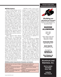
September 2014 - Maritime Reporter and Engineering News page: 14
)
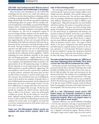
September 2014 - Maritime Reporter and Engineering News page: 14understanding of wave impact loading and the corresponding structural response of the containment system. For the validation Computation- al Fluid Dynamics (CFD) software stern wave measurements were performed on a +100 m vessel. A fi eld of 25 m behind the vessel was covered by two cameras to
-
 )
April 1980 - Maritime Reporter and Engineering News page: 32
)
April 1980 - Maritime Reporter and Engineering News page: 32, chairman emeritus, Webb Institute of Na- val Architecture, Glen Cove, N.Y. Journal of Ship Research Com- mittee—Ralph I). Cooper, head, Fluid Dynamics Program, Office of Naval Research, Department of the Navy, Arlington, Va. Marine Technology Committee —E. Scott Dillon, consultant, Sil- ver
-
 )
May 2014 - Marine News page: 59
)
May 2014 - Marine News page: 59offshore industry to identify, evaluate and then control po- tential hazards. Unlike Advanced Finite Element Analyses (FEA) or Computational Fluid Dynamics (CFD) whole ship analyses, which are collectively expen- sive, both in analysis time and money, and often only provide the structural response
-
)
May 2014 - Marine News page: 59
offshore industry to identify, evaluate and then control po- tential hazards. Unlike Advanced Finite Element Analyses (FEA) or Computational Fluid Dynamics (CFD) whole ship analyses, which are collectively expen- sive, both in analysis time and money, and often only provide the structural response
-
 )
January 1981 - Maritime Reporter and Engineering News page: 48
)
January 1981 - Maritime Reporter and Engineering News page: 48. Write 150 on Reader Service Card DAVID W. TAYLOR NAVAL SHIP R&D CENTER is seeking NUMERICAL SHIP HYDRODYNAMICISTS The Numerical Fluid Dynamics Branch of the David W. Taylor Naval Ship Research and Develop- ment Center is seeking Ph.D. level naval architects with experience or training
-
 )
March 15, 1981 - Maritime Reporter and Engineering News page: 47
)
March 15, 1981 - Maritime Reporter and Engineering News page: 47and related systems from basic concept through R&D for ship design, habitability, mass properties evaluation, passive damage con- trol, hull form, fluid dynamics and development of associated systems and production level computer- aided programs. • DEPUTY DIRECTOR, HULL GROUP (SEA 32B) The incumbent