
FPSO Retrofit Design Accelerated With CAD
Software that automatically produces loop, cable, and termination drawings from information in piping and instrumentation diagrams (P&IDs) allowed Merpro Limited to prepare electrical schematics for an offshore retrofit twice as fast as on previous projects. The retrofit involved a floating production storage and offloading (FPSO) tanker, the Bluewater Uisge Gorm, which was increasing the water cut and accumulating solids in one of its separators. Merpro designed a system that addressed both problems. The documentation for the system included 78 electrical schematics, and in a time and cost-saving move designers created "intelligent" P&IDs containing equipment specifica- tions, engineering information, and other data. Then they created loop and junction box templates using the software's drafting system. The prototypes used "tokens" to represent information such as tag number, manufacturer, model number, and so on. The software automatically generated loop, cable, and termination drawings by replacing tokens with descriptive data from the P&ID instrument index master database, making it possible to complete the drawings in six weeks.
The Uisge Gorm is situated on the Furgus Fife Oil Field in the U.K. sector of the North Sea, close to the Norwegian and Danish sectors. During the initial two years operation, being a marginal field the water cut increased quite dramatically such that the field was producing almost as much water as oil and this would continue to increase as the age of the field increased. The high water cut meant that the produced water system was running near its limit and as such to achieve the oil in water overboard discharge legislative requirements production had to be cut back, this would result in a decrease in revenue. A second problem, one of sand production, was also encountered during this period with plant shut downs having to take place at more frequent intervals to remove the solids build up in the separation vessels.
Besides the more frequent shutdowns to remove the solids, a potentially greater problem is the effect that sand has on the instrumentation and the erosive effects on pipework and valves. The existing plant like most installations in the North Sea had no facility to manage solids.
Merpro Limited was contracted by Bluewater Engineering b.v. to design a system to meet the above needs.
Merpro specializes in the design and manufacture of oil and gas processing systems primarily for the offshore sector a two-part solution was proposed for the Usige Gorm. In the past, Merpro would have generated the documentation for a project such as this by using one program to create P&IDs, AutoCAD to create electrical schematics such as junction box layouts and instrumentation loops, and a spreadsheet application to generate instrument and valve lists.
Since there was no connection between any of the programs, each schematic was started from scratch and equipment lists were created manually on spread- sheets. For junction box layouts, each line from the terminals on an instrument to the terminal rail in the junction box had to be drawn individually. To make loop drawings, someone had to draw each loop, including field devices, terminal strips, and controls, and then manually type in information such as tag number, model number, calibrations, and so on. Typically, he or she was working from the spreadsheet equipment list when making the loop drawing.
The process was time-consuming, and also inaccurate since it was possible to forget a loop, double allocate terminals etc.
On this project, Merpro decided to take a different approach. The company had recently purchased AutoPLANT from Rebis, in Walnut Creek, Calif. This family of 2-D and 3-D plant design software runs as an add-on to AutoCAD.
One of the reasons Merpro purchased this system was because they could buy only the modules they wanted. They purchased the P&ID module, the Instrumentation system, and the Data Manager.
Rather than simply drawing geometry to indicate process lines and equipment as they would with a CAD system, the new system would allow them to create intelligent P&IDs that also maintained a textual database with detailed specifications on all equipment and lines. Equipment lists could be generated automatically from the information in the P&ID database. And because Instrumentation and P&ID share a common database, once a P&ID has been produced, all other required documentation such as loop, cable, and termination drawings can be generated automatically.
When changes are made to a P&ID, they instantly ripple through the entire documentation package.
Intelligent process After the process flow diagram and process schematic were completed, they were turned over to the designers who created the P&IDs. Rather than drawing equipment and lines, adding bubbles, and putting text in the bubbles, they were able to insert pre-created equipment blocks provided by the Rebis software into the drawings. The blocks included intelligence about the equipment they described. For example, after a designer inserted a pump block, the software placed its tag number on the drawing and a description of the pump in the equipment list. As designers added equipment to the drawings, either by using pre-made blocks or by drawing their own, the master database was being populated so that when the P&ID was complete, the database was as well.
Some of the textual data was generated by the software itself. For example, if a tag number started with certain letters, it knew that this was a transmitter and it filled in the instrument description automatically.
In other cases, engineers entered information into the data sheet module from which instruments' purchase requisitions are generated..
Once the P&IDs were finished, valve and instrument lists were automatically generated from the information in the P&ID database, eliminating several weeks of manual data entry and potentially costly mistakes. Once design and documentation was finished, the 130- ton system was manufactured at Merpro's facility in Montrose. It was installed offshore, minimizing downtime for the FPSO.
Since installation of the Merpro module, flow rates to the existing process package have been increased from 80,000-bpd to almost 110,000-bpd, with resultant increased oil production of some 10,000-bpd. Solids are treated and disposed with no loss of production, and the produced water treatment package, designed for 45,000-bpd, has effectively treated up to its design limits and met the very tight environmental and legislative limits.
Circle 1 on Reader Service Card by Ken Perkins, drawing office manager and Adrian Clay, design engineer Merpro Limited, Bristol, England
Read FPSO Retrofit Design Accelerated With CAD in Pdf, Flash or Html5 edition of September 2000 Maritime Reporter
Other stories from September 2000 issue
Content
- Millennium Slated For NNS Visit page: 44A
- PBCF Aids Propulsion Efficiency page: 44A
- First Of Modified Destroyers Commissioned page: 44B
- Ties that bind page: 44B
- First Family of Design page: 8
- Unitor Launches New IT Program page: 13
- Market Forces And Technology Will Shape The Futre Of Shipping page: 17
- Bahamas Receives New RoPax Service page: 23
- Crowley Delivers Last Of Prevention Tug Series page: 23
- Image Marine Delivers Police Boat Trio page: 24
- PTC Launches New CAD/CAM Shipbuilding Solution page: 25
- SNAME 2000 Aims To Connect Leaders page: 28
- Pods for a rising market page: 31
- NNS Fixes Circle 278 on Reader Service Card ISO 9001 CERTIFIED 8365 Highway 308 South • Lockport, Louisiana 70374 Telephone: (504) 532-2554 • Fax: (504) 532-7225 • www.bollingershipyards.com Paradise s Pod page: 32
- MTU Enters The Medium Speed Fray With The 8000 page: 34
- U.S. Footprint In Germany page: 34
- Ship Noise Guide Updated page: 38
- Can the Hinge Ship Work? page: 40
- The Many Modes of Hinge-Ship page: 42
- Welcome "Lo Jack" For Ships page: 44
- lnternet@Sea page: 44
- The more things change... page: 45
- SMM 2000 Set For Hamburg page: 47
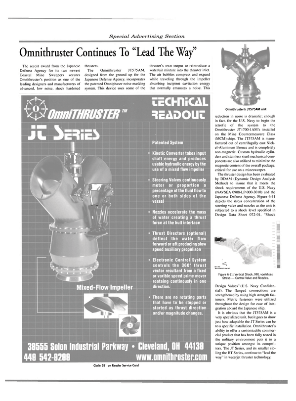
- Omnithruster Continues To "Lead The Way" page: 52
- FPSO Retrofit Design Accelerated With CAD page: 54
- Ballast Water Management & Treatment Take Center Stage page: 67
